Proactive catalyst heating

a catalyst heating and catalyst technology, applied in the direction of machines/engines, electrical control, separation processes, etc., can solve the problems of poor initial emissions, less effective catalysts at reducing emissions just after engine ignition, etc., to reduce harmful emissions, reduce the warm-up process, and reduce the time to light-off temperature

Active Publication Date: 2019-02-28
VITESCO TECH USA LLC
View PDF6 Cites 18 Cited by
  • Summary
  • Abstract
  • Description
  • Claims
  • Application Information

AI Technical Summary

Benefits of technology

[0011]One advantage of the present invention is that the catalytic emissions system is prepared for operation before ignition of the internal combustion engine. This allows for a reduction of harmful emissions to the atmosphere during warm-up of the engine. The proactive heating system of the present invention may be useful in any field that uses internal combustion engines that are routinely started from a cold state.
[0012]One embodiment of this invention includes an internal combustion engine with a filtered atmospheric air source for an intake, where a portion of the air from the air source is directed into the stream of exhaust gas by the air pump. In an alternate embodiment, instead of the air pump drawing fresh air from the filtered engine intake, the air pump draws air from its own filtered intake, or from the EVAP canister. Pulling from the EVAP canister decreases the warm-up process by providing an exothermic reaction from the fuel vapors.
[0013]The exhaust gas from the engine is directed first through an electrically heated catalyst (eHC). Immediately downstream of the eHC is another catalyst, or main catalyst, that is not electrically heated. This main catalyst performs the majority of the catalytic conversion of the emissions. There is also an air pump that pumps air from the filtered intake system into the exhaust system upstream of the eHC. The controls are designed to activate the eHC and air pump for a designated amount of time prior to engine ignition. This is controlled based on the existing temperature of the main catalyst.
[0014]Other embodiments of this invention are also possible. The proactive heating system of the present invention may be used with a turbocharged engine, a supercharged engine, or a twin-charged engine. Further embodiments may include variations in the controls logic, variations in the air pump intake, variations on the control valving which prevents exhaust gas from reaching the air pump, and variations of the after treatment catalysts.
[0015]All controls logic which are part of the present invention include the steps of activating the eHC and air pump prior to engine ignition in order to pre-heat the main catalyst. However, variations on actuating the air pump and eHC in a staggered operation or simultaneously are advantageous for decreasing the time to light-off temperature.
[0016]Valving is used to protect the air pump from engine exhaust gasses, and prevent backflow through the pump. This valving could vary with different types of valves, and different amounts of valves. Examples include, but are not limited to, passive check valves, active solenoid valves, and active pneumatic valves.

Problems solved by technology

However, when engine ignition first occurs, the engine produces the highest amount of emissions, and the catalyst is typically at ambient temperature (or some other temperature which is well below light-off temperature), such that the catalyst is less effective at reducing emissions just after engine ignition.
One of the drawbacks to these strategies is that the catalyst is below the “light-off” temperature, where conversion of emissions is greatest, resulting in poor emissions during the initial period.

Method used


Image

  • Proactive catalyst heating
  • Proactive catalyst heating
  • Proactive catalyst heating

Examples


Embodiment Construction

[0034]The following description of the preferred embodiment(s) is merely exemplary in nature and is in no way intended to limit the invention, its application, or uses.

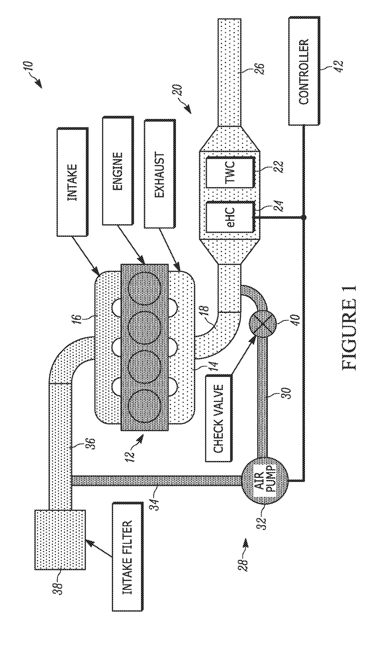
[0035]A diagram of an exhaust system for an engine having a proactive heating system including a catalyst is shown in FIG. 1 generally at 10. The exhaust system 10 is connected to an engine, shown generally at 12. More specifically, the engine 12 includes an exhaust manifold 14 and an intake manifold 16. Connected to and in fluid communication with the exhaust manifold 14 is a front exhaust pipe 18, and the front exhaust pipe 18 is connected to and in fluid communication with an exhaust treatment device, shown generally at 20. The exhaust treatment device 20 includes a three-way catalyst (TWC) 22 and an electrically heated catalyst (eHC) 24. Connected to and in fluid communication with the exhaust treatment device 20 is a rear exhaust pipe 26.

[0036]Also shown in FIG. 1 is an air transfer device, shown generally at 28....


PUM


Abstract

A proactive heating system for a vehicle, which is used to increase the temperature of an exhaust catalyst prior to ignition of an engine to reduce emissions. The proactive heating system is part of an exhaust system for a vehicle, and includes an electrically heated catalyst and an air pump, which are activated prior to engine ignition, to increase the temperature of a three-way catalyst such that the three-way catalyst is at the desired target threshold temperature, or light-off temperature, prior to engine ignition, eliminating the delay in emissions treatment after cold-start of the engine. The proactive heating system addresses the high level of untreated emissions emitted from an internal combustion engine before the catalytic emissions system reaches the light-off temperature. The proactive heating system provides heating of a catalyst to light-off temperature without combusting hydrocarbon fuel, which leads to engine out emissions.

Description

FIELD OF THE INVENTION[0001]The invention relates generally to a proactive heating system, which is part of an exhaust system, and is used to increase the temperature of an exhaust catalyst prior to ignition of an engine to reduce emissions and optimize fuel efficiency.BACKGROUND OF THE INVENTION[0002]Efforts have been made to reduce emissions in the exhaust gas produced by internal combustion engines. One of the components in the exhaust system for a vehicle used for reducing emissions is an exhaust catalyst. One type of catalyst is referred to as a “three-way catalyst.” A three-way catalyst performs three different conversions of various exhaust emissions. One type of conversion is the reduction of nitrogen oxides to nitrogen and oxygen, another type of conversion is the oxidation of carbon monoxide to carbon dioxide, and the third conversion is the oxidation of unburnt hydrocarbons (HC) to carbon dioxide and water.[0003]A catalyst is most effective at controlling exhaust emission...

Claims


Application Information

Patent Timeline
Patent Type & Authority Applications(United States)
IPC IPC(8): F02D41/02F01N3/30F01N3/36F02M25/08F01N3/08F01N3/32F01N3/10F01N3/20B01D53/94
CPCF02D41/025F01N3/303F01N3/36F02M25/0836F01N3/0835F01N3/32F01N3/101F01N3/2013F01N3/2033B01D53/9454F01N2610/03F01N2610/102F01N3/2006F01N2240/12F01N2240/16F02D41/0035F02D41/042Y02T10/12Y02A50/20
Inventor MCKAY, BRIANBARGMAN, BEN
Owner VITESCO TECH USA LLC
Why Eureka
Try Eureka