Device and method for generating charged particle beam pulses

a technology of charged particle and beam pulse, which is applied in the direction of basic electric elements, electric discharge tubes, electrical apparatus, etc., can solve the problems of synchronization of a femtosecond laser, jitter left, and order of magnitude higher repetition rate of electron pulses with respect to optical pulses, and achieve accurate positioning of deflection units.

Inactive Publication Date: 2019-03-28
TECH UNIV DELFT
View PDF0 Cites 3 Cited by
  • Summary
  • Abstract
  • Description
  • Claims
  • Application Information

AI Technical Summary

Benefits of technology

[0049]In an embodiment, the deflection unit is mounted onto a manipulator device for moving the deflection unit at least in a plane substantially perpendicular to an optical ...

Problems solved by technology

One of the problems of the prior art electrostatic beam blanker is the synchronization of a femtosecond laser, typically with repetition rates of 100 MHz, jitter free to a beam blanker working with GHz electrical signals.
However, still there will be some jitter left by locking an electrical circuit t...

Method used


Image

  • Device and method for generating charged particle beam pulses
  • Device and method for generating charged particle beam pulses
  • Device and method for generating charged particle beam pulses

Examples


Embodiment Construction

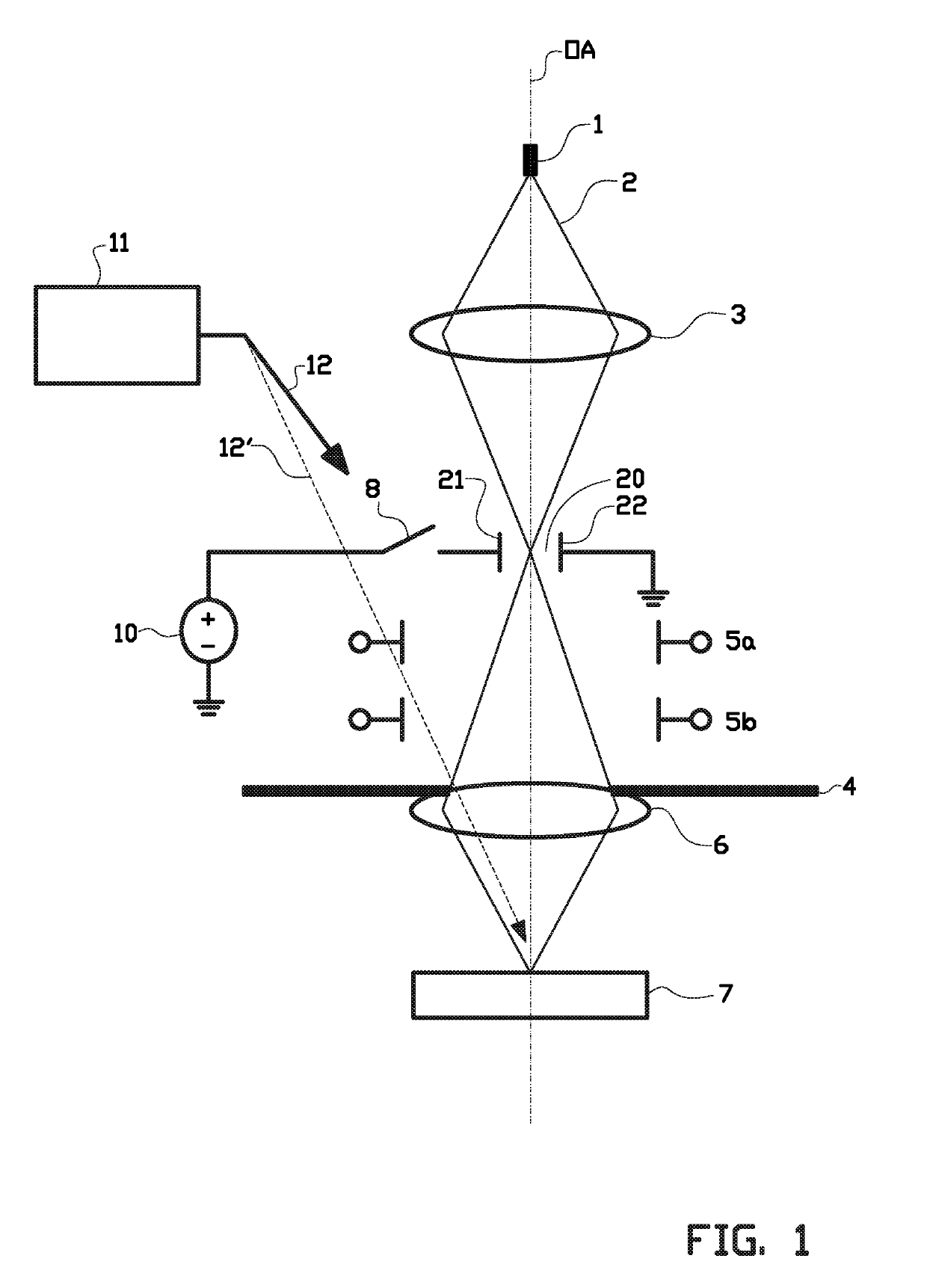
[0073]FIG. 1 schematically shows an apparatus for inspecting a surface of a sample 7, such as a Scanning Electron Microscope with a deflection unit 20 according to the invention. The apparatus may also be a transmission electron microscope or a scanning transmission electron microscope, for example.

[0074]The apparatus comprises a charged particle generator, in particular an electron source 1 with high brightness. The electron source 1 comprises for example a Schottky source or a cold field emitter, which is arranged for emitting a beam of electrons 2 along an electron-optical axis OA. In addition or alternatively the electron source 1 can also be a sharp metal tip where electrons are extracted using femtosecond optical pulses.

[0075]The apparatus further comprises a charged particle optical system for projecting and / or focusing the electron beam 2 into the sample 7. The charged particle optical system comprises a magnetic or electrostatic lens 3 or a combination of lenses to focus th...


PUM


Abstract

Disclosed is a device for, in combination with a stop having an aperture, generating charged particle beam pulses, an apparatus for inspecting a surface of a sample, and a method for inspecting a surface of a sample. The device includes a deflection unit which is arranged for positioning in or along a trajectory of a charged particle beam. The deflection unit is arranged for generating an electric field for deflecting said charged particle beam over the stop and across the aperture. The device also includes an electrical driving circuit for providing a periodic signal. The electrical driving circuit is connected to the manipulation unit via a photoconductive switch, wherein the photoconductive switch is arranged for: substantially insulating the deflection unit from the electrical driving circuit, and for conductively connecting the deflection unit to the electrical driving circuit only when said photoconductive switch is illuminated by a light beam.

Description

BACKGROUND[0001]The invention relates to a beam deflecting device, fast enough to be used for Ultrafast Electron Microscopy (UEM). Lately there is a demand in studying time dependent effects with time resolutions in the picosecond and femtosecond range, in an electron microscope.[0002]A charged particle imaging apparatus, like an electron microscope, is capable to image the constituents of a sample at very small detail (high resolution), higher than can be achieved with a light microscope, but the capability to also follow processes at femtosecond and picosecond time scales is absent, in general. For UEM it is necessary to create a pulsed electron beam, where the pulse length will set the temporal resolution of the UEM.[0003]The U.S. Pat. No. 8,569,712 for example, discloses an electrostatic beam deflector for a particle-optical apparatus, in which a diaphragm comprising an aperture is used for interrupting a beam of charged particles. The beam deflector is used to sweep the beam of...

Claims


Application Information

Patent Timeline
IPC IPC(8): H01J37/244H01J37/147H01J37/22H01J37/04H01J37/28
CPCH01J37/244H01J37/1474H01J37/226H01J37/045H01J37/22H01J37/28H01J2237/043H01J37/21H01J2237/2814H01J2237/0432H01J2237/2482
Inventor KRUIT, PIETERWEPPELMAN, IZAAK GERRIT CORNELIS
Owner TECH UNIV DELFT
Why Eureka
Try Eureka