
Process for manufacturing a false nail

a manufacturing process and nail technology, applied in the field of false nail production, can solve the problems of limiting interest, affecting the longevity of varnish, and not being able to lengthen the nail or unify the length, so as to facilitate physical and/or chemical degradation, limit the damage of the layer, and be easily used for additive manufacturing

Pending Publication Date: 2019-04-11
LOREAL SA
View PDF7 Cites 1 Cited by
  • Summary
  • Abstract
  • Description
  • Claims
  • Application Information

AI Technical Summary

Benefits of technology

The patent text describes how nail makeup is used to improve the appearance of nails and protect them from damage. It also allows for the removal of unnecessary parts and the shape of false nails. The technical effects of the patent text revolve around helping to make nails stronger and more visually appealing.

Problems solved by technology

However, they do not make it possible to lengthen the nails or to unify their length and they are, furthermore, relatively fragile.
However, these patterns must be made by a skilled person and the lifetime of the varnish limits the interest thereof, with regard to the required investment.
The major drawback of patches is that they can only be presented to users in given forms that do not correspond to the exact contour of the nail.
Thus, patches require cutting-out work, which it is not possible to do once the patch has been stuck on.
Now, it has been noted that many people have difficulty in performing this cutting-out.
Moreover, patches cannot lengthen the nails, since, if the patch exceeds in length, it very quickly bends under the effect of impacts.
However, this technique is limited since the cutting-out work can damage the pattern, which then becomes worthless.
However, this technique requires considerable skill and takes a long time, conventionally more than 30 minutes.
The maintenance following the application takes up an appreciable amount of time, since, when the nail grows, it is necessary to rework the resin and to pour a new coat.
Another drawback of this technique lies in the fact that the false nail thus obtained cannot be removed at any time.
This limits its development, since many women desire decoration and / or lengthening for a limited period.
Knowing that they cannot take off their false nails easily, they are unwilling to give them a try, and when they do dare to, they prefer limited lengthening and decorations.
Another major drawback is that the natural nail suffers from not being in the open air and, if it remains covered with resin for a long time, it may soften or develop infections.
The adhesive must moreover be placed on only one face without running or overflowing around the nail, which excludes adhesive application techniques by dipping or spraying an adhesive onto the nail, all the more so since certain adhesives cannot be applied by spraying.

Method used


Image

  • Process for manufacturing a false nail
  • Process for manufacturing a false nail
  • Process for manufacturing a false nail

Examples


example 1

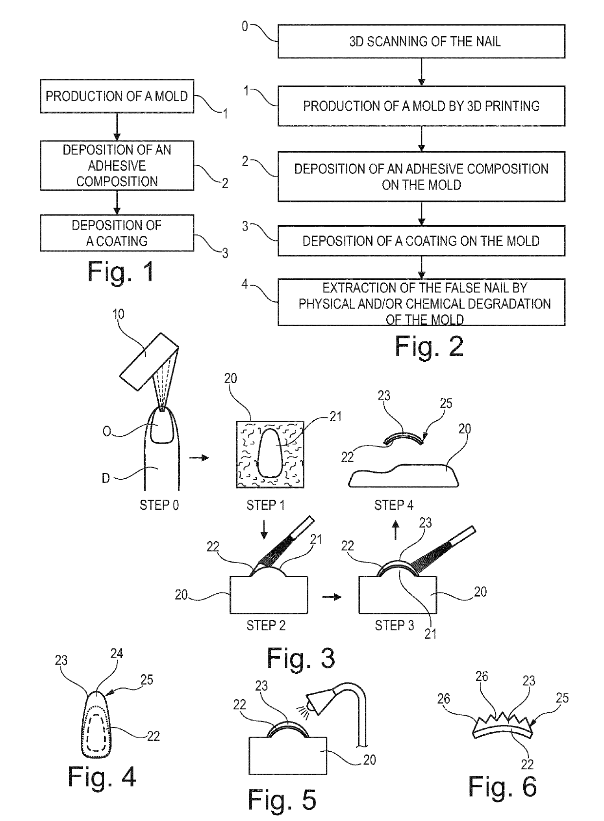
[0436]The end of a person's finger is taken by a 3D scanner. By file data processing, the nail part of the end of the finger is isolated and a 3D file of the surface of the nail is produced. From this 3D file comprising the 3D digital data of the acquisition of the relief of the nail, a “mold” 3D digital object is created.

[0437]The 3D digital data of this “mold” 3D digital object are then used to produce, via a 3D printer, for example the printer sold under the brand name ProJet® 3500 HDMax by the company 3D Systems, a mold made of a first material formed in this example from wax, especially the wax sold under the brand name VisiJet® S300 by the company 3D Systems.

[0438]The adhesive composition is then made with the following mass proportions, relative to the total mass of the composition:[0439]Kraton G1701 5%,[0440]Regalite R1100CG 15%[0441]Kaydol 5%[0442]Isoamyl acetate in quantity sufficient for 100%.

[0443]A layer of this composition is deposited by brush, on the mold, in a mass ...

example 2

[0446]A support is made by 3D printing reproducing five nail molds made of a first material.

[0447]This support is then scanned in 2D and the projected surfaces of the nail parts are extracted, omitting all the surfaces between the nail parts.

[0448]This file is introduced into a printing machine, for example a printer from the company Scodix. Before introducing the mold into the machine, it is spread, using a brush, with a layer of about 100 μm of an adhesive composition having the following formula:[0449]Kraton G1701 5%,[0450]Regalite R1100CG 15%[0451]Kaydol 5%[0452]Isoamyl acetate qs 100%

[0453]The mold thus covered is then placed in the Scodix printer. The Scodix printer is set up, by means of its positioning system. Thus, on the basis of the 2D file, it delivers the photo-polymerizable ink sold under the name PolySENSE® 100 by the company Scodix onto the nail parts of the support.

[0454]The machine is controlled so that it prints, with the photo-polymerizable ink forming the second...

example 3

[0456]A 3D object is made by additive manufacture, using the Visijet S400 equipment sold by the company 3D Systems. The object is a mold and represents a nail.

[0457]A layer of 1 mm of water-based adhesive, known under the brand name Uhu®, is then deposited onto the surface of the mold.

[0458]A coating 500 μm thick is then produced on this coated surface by applying a UV gel known under the brand name CND Shellac Xpress 5 top coat. The whole is placed under a UV lamp for 3 times 1 minute with an interval of one minute between each irradiation. The lamp is known under the brand name CND Shellac 36 W.

[0459]The false nail thus obtained is detached from the mold.


PUM

PropertyMeasurementUnit
melting pointaaaaaaaaaa
lengthaaaaaaaaaa

Abstract

The present invention relates to a process for manufacturing a false nail, comprising the following steps: a) producing by additive manufacture, from 3D digital data originating from the acquisition of a relief, especially that of the finger intended to receive the false nail, a mold using a first material, b) depositing onto the mold a layer formed from at least one adhesive composition, c) depositing onto the mold at least one layer of a coating of a second material, different from the first, so as to form the false nail.

Description

[0001]The present invention relates to the production of false nails, also known as artificial nails.PRIOR ART AND TECHNICAL PROBLEM[0002]The making up of natural nails on the hands or feet is directed toward giving them a better colored appearance and / or toward enlarging, lengthening or unifying them, modifying their surface appearance, making them glossy or producing decorative or expressive patterns thereon. Nail makeup also allows the nails to be strengthened to protect them against impacts, friction or liquids.[0003]The techniques available at the present time for achieving these objectives are, depending on the case, more or less satisfactory.[0004]Varnishes are effective for giving a colored and / or glossy appearance. However, they do not make it possible to lengthen the nails or to unify their length and they are, furthermore, relatively fragile. To a certain extent, varnishes allow patterns to be formed. However, these patterns must be made by a skilled person and the lifeti...

Claims


Application Information

Patent Timeline
Patent Type & Authority Applications(United States)
IPC IPC(8): A45D31/00B29C64/386B29C41/22B29C41/42B29C33/38B29C35/08B33Y10/00B33Y50/00B33Y70/00B33Y80/00
CPCB33Y70/00B33Y50/00B29K2105/0097B29K2891/00B29C64/112B29K2091/00B29C2035/0827B29L2009/00B29C64/386A45D31/00B29L2031/718B29C41/22B29C41/42B29C33/3842B29C35/0805B33Y10/00B33Y80/00
Inventor GIRON, FRANCKSAMAIN, HENRIDUCASTIN, PIERRE
Owner LOREAL SA
Learn More