Device for sterilizing an object, the device having a stream deflector

a technology of a device and an object, which is applied in the direction of disinfection, electric discharge tubes, constructions, etc., can solve the problems of certain objects being damaged, objects being damaged during treatment, packaging can also be damaged in that type of device, etc., and achieves the effects of reducing the speed of the species, reducing the probability of disappearance, and increasing the kinetic energy

Inactive Publication Date: 2019-04-25
SOC POUR LA CONCEPTION DES APPL DES TECHN ELECTRONIQUES SATELEC
View PDF5 Cites 1 Cited by
  • Summary
  • Abstract
  • Description
  • Claims
  • Application Information

AI Technical Summary

Benefits of technology

[0016]Specifically, firstly the central portion has a greater concentration of metastable species than does the peripheral portion, which metastable species constitute species that are aggressive relative to the object for treatment or relative to the packaging in which the object is present. This difference in concentration can be explained by the fact that the metastable species in the peripheral portion have a greater probability of disappearing as a result of collisions with the wall of the duct, given that they are closer to that wall. Secondly, the species in the central portion follow a straight line path at a speed that is greater than the speed of the species that are present in the peripheral portion, thereby giving them higher kinetic energy that might damage the object for treatment or its packaging on impacting thereagainst.
[0017]The invention proposes positioning a deflector constit

Problems solved by technology

Applying a temperature higher than 70° C. can raise problems and lead to certain objects being damaged, e.g. when the object includes portions made of polymer materials.
Nevertheless, the object can b

Method used


Image

  • Device for sterilizing an object, the device having a stream deflector
  • Device for sterilizing an object, the device having a stream deflector

Examples


Embodiment Construction

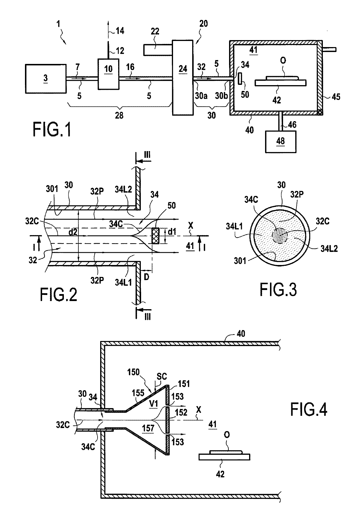
[0038]FIG. 1 is a diagram showing a sterilization device 1 configured to sterilize an object O by treatment with a post-discharge stream resulting from a nitrogen plasma.

[0039]The device 1 comprises a duct 5 having a first segment 28 putting a compressor 3 into communication with a plasma generator 20. The first segment 28 has a nitrogen filter element 10 situated between the compressor 3 and the plasma generator 20.

[0040]A stream of compressed air 7 coming from the compressor 3 flows through the first segment 28 to the filter element 10. The filter element 10 is constituted by a known element that is configured to separate nitrogen from oxygen in the compressed air stream 7. After passing through the filter element 10, a nitrogen stream 16 flows through the first segment 28 to the plasma generator 20. The oxygen 14 that is separated from the nitrogen is discharged via an exhaust duct 12.

[0041]The first segment 28 serves to deliver the nitrogen stream 16 to the plasma generator 20. ...


PUM


Abstract

A sterilization device for sterilizing an object comprises a sterilization chamber defining a treatment zone in which the object for sterilizing is to be positioned; a nitrogen source; a plasma generator in communication with the nitrogen source; and a duct putting the plasma generator into communication with the sterilization chamber and through which a post-discharge stream resulting from a plasma produced by the plasma generator is to flow towards the sterilization chamber. The duct defines an injection orifice for injecting the post-discharge stream into the sterilization chamber. The device has a deflector for deflecting the post-discharge stream and positioned in the sterilization chamber facing a central portion of the injection orifice, upstream from the treatment zone. The deflector is configured to deflect the flow of a central portion of the post-discharge stream as introduced through the central portion of the injection orifice.

Description

[0001]The present invention relates to a device for sterilizing an object with a post-discharge stream resulting from a plasma produced by a plasma generator, and the invention also relates to a method of sterilization using such a device.BACKGROUND OF THE INVENTION[0002]It is known to sterilize objects by means of an autoclave in which the object to be sterilized is raised to a determined high temperature, of the order of 120° C., and for this to be done during determined time periods with cycles that are specified by legislation.[0003]Applying a temperature higher than 70° C. can raise problems and lead to certain objects being damaged, e.g. when the object includes portions made of polymer materials.[0004]Methods enabling sterilization to be performed at lower temperatures have consequently been developed in order to reduce the damage to objects while they are being treated.[0005]In this context, devices have been proposed that make use of a post-discharge stream from a plasma. T...

Claims


Application Information

Patent Timeline
IPC IPC(8): A61L2/14A61L2/24H05H1/24
CPCA61L2/14A61L2/24H05H1/24H05H2245/1225A61L2202/122A61L2202/24H01J37/32357H01J37/3244H05H2245/36B05B1/00
Inventor CASABONNE, THIERRYVILLEGER, SANDRINEBENOIT, MARIE-AGNES
Owner SOC POUR LA CONCEPTION DES APPL DES TECHN ELECTRONIQUES SATELEC
Why Eureka
Try Eureka