System and method for removing moisture from water laden structures

a technology of water laden structures and moisture removal, applied in the direction of drying machines, heating arrangements, light and heating equipment, etc., to achieve the effect of less time for assembling, reconfiguring and disassembling, and less clutter

Inactive Publication Date: 2019-05-02
INJECTIDRY SYST
View PDF5 Cites 0 Cited by
  • Summary
  • Abstract
  • Description
  • Claims
  • Application Information

AI Technical Summary

Benefits of technology

[0031]Another fundamental advantage of the invention is the means for improved efficiency in mobilization and demobilization. Specifically, the configuration of the new system is considerably less cluttered, takes less time to assemble, deploy, reconfigure and disassemble, thereby saving considerably in labor cost.
[0032]Prior systems involved a trunk line hose feeding a manifold, which in turn distributed the air through a plurality of long tubes (see FIG. 1). The system of the invention instead distributes the tubes along the trunk line hose (see FIG. 2). As a result, considerably less tubing is required, and no manifold is required at all, resulting in lower manufacturing costs and a less expensive overall system for the user.
[0033]In addition, in a preferred embodiment of the new system, the tubes are preassembled, that is already attached in the trunk hose. Thus, the user need not even affix any of the tubes to a manifold. This feature, plus the generally less cluttered configuration as shown in FIG. 2 relative to FIG. 1, results in a much easier system to use in the field.
[0034]In addition, the new configuration results in less interference with the afflicted structure. The shorter tubes being affixed along the trunk enable the system to be deployed in most applications around the perimeter of the afflicted room, leaving most of the room available for use.
[0035]The new configuration also distributes the air more efficiently in the sense of requiring less energy (typically electrical) and less tubing material per unit of air moved. By delivering air at the point of need, there is an elimination of tubing, eliminating need for air to travel through 3-4 unnecessary feet of tubing for each injector, faster setup, less trip hazard, less labor to carry in and setup. Thus, in summary, presently the drying art practiced has manifolds which are placed at infrequent intervals disposed along a trunkline. The disadvantages are in the area of messiness, excessive amounts of tubing required, trip hazard, increased friction due to extra lengths of tubing required and high labor costs to setup. The present invention solves each of these problems.
[0036]Obtaining all of the advantages of my new preferred configuration could not be effected simply by multiplying the number of manifolds of the prior systems, in part because the labor and material costs would be prohibitive. Instead, to capture all the advantages of the preferred embodiment, a fundamentally new approach was required. Specifically, the distribution of the air more efficiently to the afflicted areas, without doubling back, required a fundamentally different configuration. The configuration of the preferred embodiment of the present invention provided that fundamental difference. Specifically, it involved tubing along the main trunk hose (compare FIG. 1 to FIG. 2). However, this configuration had to be accomplished in a manner that would retain the integrity of the main trunk hose, and was inexpensive and easy to use. Of course, some features and advantages of my preferred embodiment could be used even with the earlier configuration. (e.g. injectors with locking tabs). But, the system as a whole works best in conjunction with my new configuration.

Problems solved by technology

Unwanted water introduced by flooding, precipitation or otherwise causes millions, if not billions, of dollars of damage to structures every year.
In addition, it left the structure relatively unusable for an undesirably long period.
While this resulted in some improvement in many cases, generally, the results were still not satisfactory.
The obvious disadvantage of such approaches is that they were so destructive as to require significant repair and / or replacement of the structure after the drying process, resulting in greater cost and often the loss of use of the structure for a longer period than would be the case without the destruction.
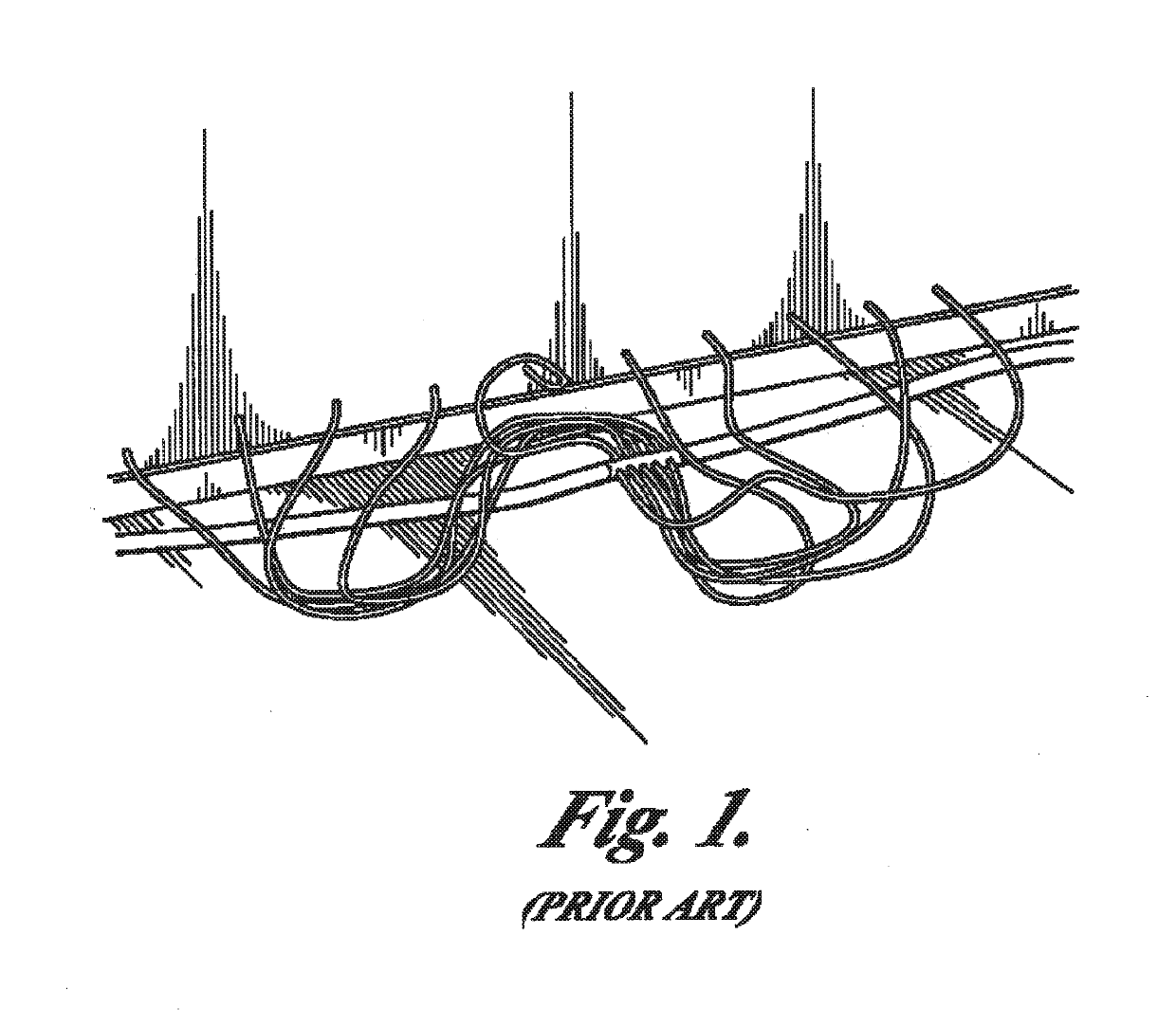
While this system was a significant advance over prior systems, significant problems remained.
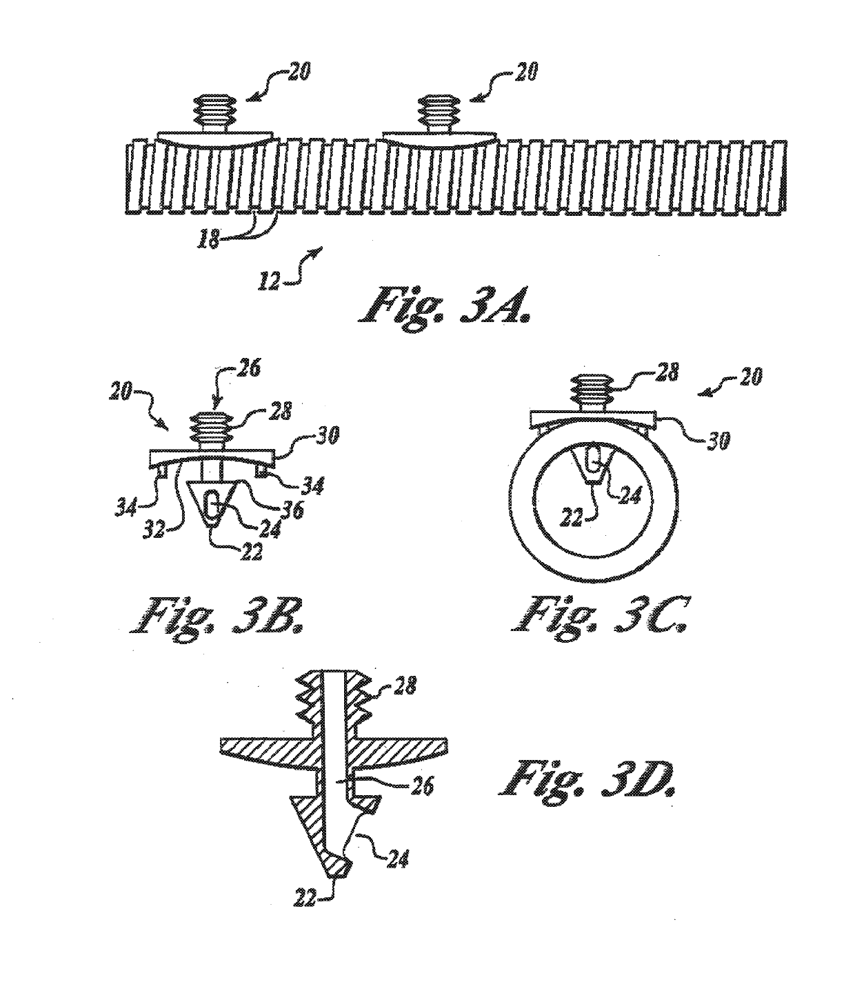
(1) Excessively destructive intrusion. Specifically, the prior system required that a plurality of relatively large sized holes be created in the structure. For example, in a high-density material such as wood, a hole in the approximate range of 3 / 16″ to 7 / 16″ diameter would be required. Holes this large require more effort in repair than would be required with smaller holes. While some prior systems have attempted to utilize smaller holes, the required air injectors were so small that they lacked convenient and effective means for preventing accidental withdrawal without damage to the structure. For example, when an injector was inserted into a wet sheetrock ceiling, the injector would have a tendency to fall out, especially in positive pressure mode. To date, previous attempts to prevent this problem have either not been effective, or have had undesirable side-effects, such as larger holes to accommodate fletching for friction to prevent withdrawal, angled penetration tending to cause damage upon removal, and threads for screwing in the injectors tending to cause a suboptimal amount of labor in the field.
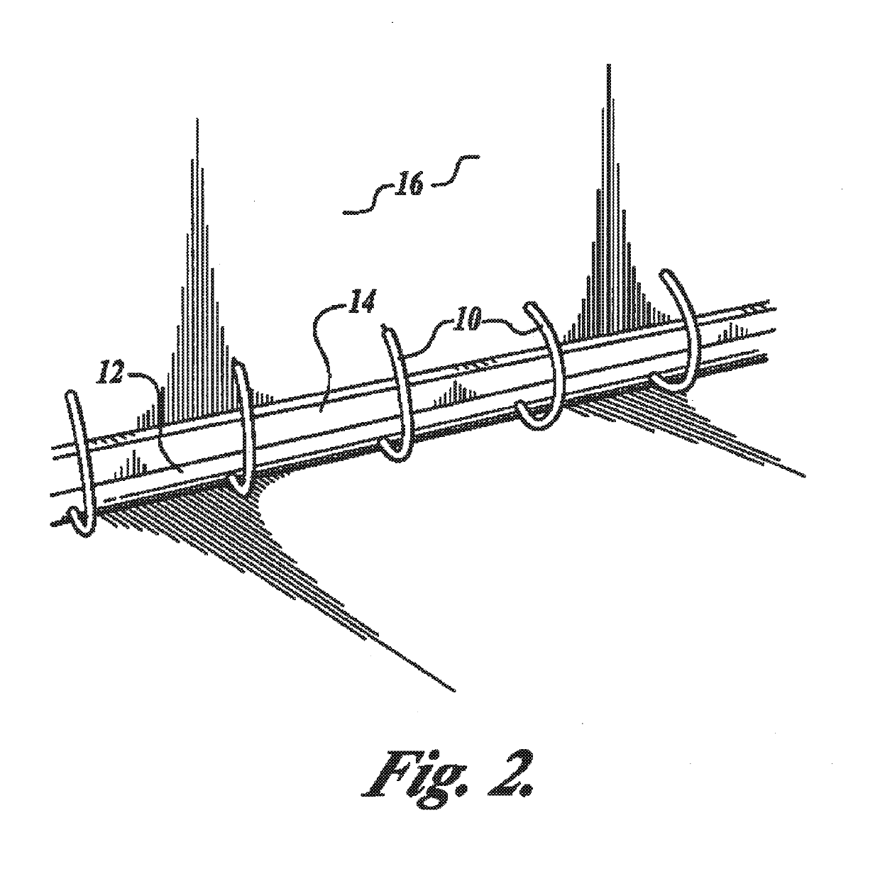
However, the hole in the distal end was too close to the end of the injector and thereby resulted in frequent clogging with wet drywall or other debris or matter within the wall or floor cavity.
Because of the small surface area available at the distal end, the extra holes could not be large enough to avoid clogging.
(3) Inefficiency and Expense in Mobilization and Demobilization.
Perhaps the biggest problem with prior systems was the relatively large amount of labor required to assemble, reconfigure and disassemble them in the field.
Another disadvantage of my prior system, and all other drying systems of which I am aware, is the significant intrusion and interference with the structure being dried.
That is, as a practical matter, while prior systems are being used to dry a structure, it is nearly impossible for the usual occupants of the premises being dried to conduct business therein.
For example, in an office building, the office tenants must generally not return until the job is completed due to the extensive tangle of blowers, hoses and tubes radiating in all directions throughout the afflicted structure.
In most prior systems also, the blowers are too loud to enable work in the structure until the job is completed.
(5) Inefficient airflow.
Prior systems moved air inefficiently.
This inefficiency was an inherent feature of the general configuration of my prior system, in that a main trunk line hose would transmit the air to a manifold, typically in the center of a room or wet area, and the manifold would then disperse the air through tubes all about the room.
Or, conversely, given a maximum amount of pressure sustainable by the blower in the system, the friction in the inefficient distribution of the prior systems would leave that much less effective air movement for actual drying at the point of the wet surface.
For much the same reason, the prior systems waste a considerable amount of material.
This not only creates more manufacturing cost and labor in the field, but also tends to clutter the afflicted structure to the point of presenting a hazardous condition for occupants, such as by increased risk of tripping.
Special Difficulties with Hardwood Floors
Each of the foregoing difficulties with prior systems applied to drying any part of any structure in general, whether walls, ceilings, cabinets, or floors, or any cavities therein.
However, particular difficulties are presented with hardwood floors.
Hardwood floors, when damaged by excess moisture, can be very difficult to dry.
In such cases, with current systems, the owner's alternatives are not good.
However, unless the contractor is careful and accustomed to repairing water-damaged structures, hardwoods are sometimes re-installed over damp subfloors.
In addition, total replacement is generally very costly.
Another disadvantage is the total time the average home or office is unusable or substantially unusable.
This delay dramatically increases the total cost of the loss because of additional living expenses or loss of use.
A further disadvantage is that sometimes the wood cannot be matched to the owner's satisfaction.
The first option of blowing air across the surface does almost no good.
Dehumidifying accompanied by tenting seems good on the face but seldom works adequately and often causes the wood to check and crack.

Method used


Image

  • System and method for removing moisture from water laden structures
  • System and method for removing moisture from water laden structures
  • System and method for removing moisture from water laden structures

Examples


Embodiment Construction

[0069]FIG. 1 illustrates the prior art as set forth in U.S. patent application Ser. No. 08 / 890,141 and serves as a basis to explain advantages of the active hoseline feature of present invention.

[0070]FIG. 2 illustrates the general configuration and context for the subsequent figures and description of the invention. It will be appreciated that while the tubes 10 of FIG. 2 are of uniform and short relatively short length, and of uniform frequency along hose 12 for drying wall 16 just above baseboard 14, the tubes 10 can be of any length, or of any frequency of distribution, regular or irregular, along hose 12. For example, in some applications it may be desirable for alternate tubes 10 to be long enough to reach a ceiling above the wall 16. In many applications, the preferred frequency of tube distribution along hose 12 will be 8 inches, such that two tubes 10 can be supplied between each wall cavity, such wall cavities (formed by studs within the wall) generally being approximately...


PUM


Abstract

The invention provides an improved method of drying wet or water damaged surfaces using a vacuum source, a manifold, and a plastic sheet covered grid having a lattice formation with spaces to permit the passing of moisture and air from and beneath the surface to the vacuum source.

Description

PRIORITY CLAIM[0001]This application is a continuation and claims priority from U.S. patent application Ser. No. 10 / 785,383 filed Feb. 24, 2004, which is a continuation-in-part of and claims priority from U.S. patent application Ser. No. 10 / 605,267 filed Sep. 18, 2003, now U.S. Pat. No. 6,886,271; which is a divisional of and claims priority from U.S. patent application Ser. No. 09 / 516,827 filed Mar. 1, 2000 now U.S. Pat. No. 6,647,639; and claims the benefit of U.S. provisional application Ser. No. 60 / 123,401 filed Mar. 8, 1999; each of the foregoing applications is incorporated by reference in its entirety as if fully set forth herein.FIELD OF THE INVENTION[0002]This invention relates generally to systems and devices for removing unwanted and harmful moisture from wet and / or water damaged structures using positive and negative pressure sources.BACKGROUND OF THE INVENTION[0003]Unwanted water introduced by flooding, precipitation or otherwise causes millions, if not billions, of dol...

Claims


Application Information

Patent Timeline
Patent Type & Authority Applications(United States)
IPC IPC(8): F26B21/00F26B23/10
CPCF26B21/00F26B21/004F26B23/10
Inventor STORRER, ERNEST J.STORRER, ERIC SEAN
Owner INJECTIDRY SYST
Why Eureka
Try Eureka