
Variable areal density cross-plied fiber-reinforced composite ballistic material

a fiber reinforced composite material and areal density technology, applied in the field of areal density cross-plied fiber reinforced composite ballistic materials, can solve the problems of reducing the ability of fibers to stay in tension, compromising effectiveness, and affecting the quality of woven stab/spike resistant fabric articles of the related art, and achieve the effect of enhancing article flexibility

Active Publication Date: 2019-05-02
HONEYWELL INT INC
View PDF0 Cites 6 Cited by
  • Summary
  • Abstract
  • Description
  • Claims
  • Application Information

AI Technical Summary

Benefits of technology

The patent is about making materials from non-woven fabric that can resist stabbing and ballistic impacts. The fabric is made up of layers that are attached together, but not fixed in position, allowing them to shift in response to the impact. The layers have areas of different thickness, which makes the fabric flexible. This makes the material stronger and more resistant to damage.

Problems solved by technology

Fiber crimping reduces the ability of the fibers to stay in tension and immediately absorb the energy of a projectile, compromising their effectiveness.
Nevertheless, woven stab / spike resistant fabric articles of the related art remain imperfect.
Creating woven fabrics of such high density requires the use of very fine, low denier per filament (dpf) yarns / yarn bundles that are expensive to manufacture and difficult to weave.
Depending on the fiber type, such low dpf yarns also have comparatively low breaking strength relative to higher dpf yarns and therefore they are less effective at preventing backface deformation when used to form ballistic resistant composite articles.
Also, the use of such fine yarns typically requires that they be highly twisted and / or highly commingled to be processed into fabrics, but the fine yarns are delicate and often break during twisting or commingling, keeping productivity low.
Composites formed from twisted fibers are also less effective at stopping bullets or other projectiles than composites formed from untwisted fibers.
Fabrics that require coatings also have drawbacks, such as reduced flexibility or undesirable added weight.

Method used


Image

  • Variable areal density cross-plied fiber-reinforced composite ballistic material
  • Variable areal density cross-plied fiber-reinforced composite ballistic material
  • Variable areal density cross-plied fiber-reinforced composite ballistic material

Examples


example 1

[0086]Several identical 38.1 cm×38.1 cm square stab / spike / ballistic resistant flexible packs are prepared for spike and stab testing. Each pack is formed by stacking together a group of layers of fabric A and a group of layers of fabric B. The layers in the stacks are not bonded to each other but are held together by taping together the four edges of the packs with generic commercially available packaging tape to hold the layers in the proper orientation during testing.

[0087]Each layer of fabric A is a non-uniform layer comprised of a single sheet (single ply) of non-woven, axially oriented (unidirectional) fibers having a non-uniform thickness and non-uniform areal density. The fibers are high strength, high modulus aramid fibers and the coated with a thermoplastic polyurethane polymer. The aramid fibers are manufactured by Teijin Inc. and have a breaking strength of 267 N and a Chord modulus of 91 GPa. Each A layer comprises 85% by weight of the fiber and 15% by weight of the poly...

example 2

[0091]An identical 38.1 cm×38.1 cm square flexible pack of this disclosure as produced in Example 1 is subjected to flexibility testing and compared to a commercially available stab resistant material (from Barrday, Inc. of Cambridge, Ontario, Canada) comprising a woven, coated aramid fabric. The comparative test sample was prepared by stacking 29 layers of the material and taping the edges of the stack as done for the new material of this disclosure. The flexibility test consists of flexing the test samples through an opening of approximately 100-mm (4 inches) and measuring extension (deflection) of the material when impacted with a metal ball plunger having a diameter of approximately 25 mm (1 inch). The plunger is lowered down to fabric extensions of 12.5 mm, 25 mm and 37 mm and the force required to reach these levels of fabric extension was measured by an Instron testing machine (Model 4505) to compare levels of flexibility of the two materials, both of which had identical area...

example 3

[0092]Three additional flexible packs of this disclosure similar to those formed in Example 1 are subjected to ballistic testing, except each pack has an areal density of 3.80 kg / m2. Each pack is subjected to ballistic testing separately on a calibrated clay backing against 9 mm, 127 grain FMS Remington bullets following National Institute of Justice test Standard NIJ 0101.06. Several of the bullets are fired to determine the industry standard V50 velocity for the material where half of the bullets were fired at a velocity to penetrate the shoot pack and the other half were fired at a reduced velocity so that bullets did not penetrate the shoot pack. The average V50 value of each of the three shoot packs is expected to be greater than 350 m / s.


PUM

PropertyMeasurementUnit
Lengthaaaaaaaaaa
Lengthaaaaaaaaaa
Thicknessaaaaaaaaaa

Abstract

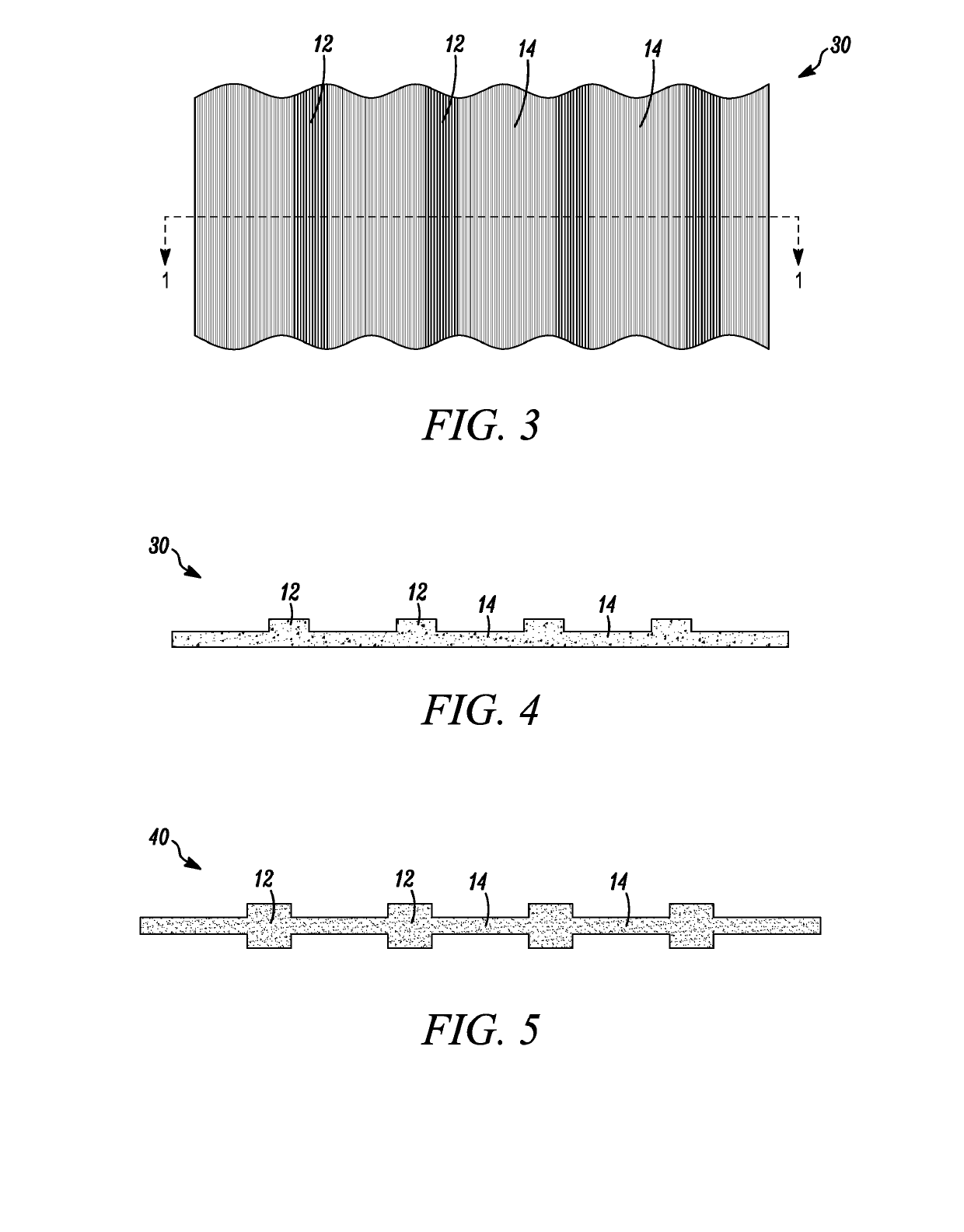
This technology relates materials that are stab, spike and ballistic resistant and to stab, spike and ballistic resistant composite articles incorporating uniaxially oriented, non-woven fabrics. A fabric layer having a non-uniform areal density is formed having thick areas and thin areas, the thick areas having a greater filament / tape concentration compared to the thin areas. In said thick areas, agglomerated tapes / filaments will protrude from the fabric layer surface. Additional layers are then adjoined with the non-uniform layer to form a panel that has stab, spike and ballistic resistance, with protrusions at least partially spacing the additional layers from full, direct contact with the surface of the non-uniform fabric layer to thereby enhance flexibility and stab, spike and ballistic resistance of the whole.

Description

CROSS-REFERENCE TO RELATED APPLICATION[0001]This application claims the benefit of co-pending U.S. Provisional Application Ser. No. 62 / 578,577, filed on Oct. 30, 2017, the disclosure of which is incorporated by reference herein in its entirety.BACKGROUNDTechnical Field[0002]This technology relates to materials that are stab, spike and ballistic resistant and to stab, spike and ballistic resistant composite articles incorporating uniaxially oriented, non-woven fabrics.Description of the Related Art[0003]High tenacity fibers, such as SPECTRA® polyethylene fibers, are known to be useful for the formation of articles having excellent ballistic resistance. Ballistic resistant articles formed from high tenacity tapes are also known. Articles such as bullet resistant vests, helmets, vehicle panels and structural members of military equipment are typically made from fabrics comprising high tenacity fibers or tapes because of their very high strength to weight performance. For many applicati...

Claims


Application Information

Patent Timeline
IPC IPC(8): F41H5/04
CPCF41H5/0485F41H5/0492F41H1/02B32B5/022B32B2571/02B32B2262/0269B32B5/06B32B27/36B32B5/028B32B27/34B32B2307/54B32B2250/05B32B2262/0253B32B2255/02B32B2250/02B32B2307/558B32B2307/52B32B7/05B32B27/308B32B2260/023B32B2250/03B32B27/32B32B3/263B32B27/12B32B2262/101B32B27/302B32B2262/0276B32B2262/0246B32B2260/046B32B2307/546B32B2255/26B32B5/12B32B7/08B32B27/40B32B2307/516B32B27/306B32B5/10B32B2262/0223B32B2270/00B32B19/06B32B5/026B32B27/365B32B2262/14B32B2307/732B32B27/30B32B5/08B32B5/26B32B3/30B32B2307/514
Inventor BHATNAGAR, ASHOKDAVIS, GREGORY A.STEENKAMER, DAVID ANDREWWAGNER, LORI L.
Owner HONEYWELL INT INC
Learn More