
Device and method of motion control

Active Publication Date: 2019-05-02
POLARWORKS AS
View PDF0 Cites 4 Cited by
  • Summary
  • Abstract
  • Description
  • Claims
  • Application Information

AI Technical Summary

Benefits of technology

The linearization module described in this patent provides better accuracy, performance, and speed than previous versions. It also results in a system that is less noisy, vibrates less, has better loop stability, and requires less maintenance.

Problems solved by technology

Such prior art methods and devices, whether continuous, such as an analog system or discreet, such as a digital system, suffer from numerous weaknesses including: poor response to varying desired position or velocity; instability, poor response to varying loop gain; poor response in non-linear systems, poor response in non-symmetric systems, and an inability to adapt constants used in PID terms to actual or dynamically changing system characteristics.
Such systems suffer from noise, vibration, and non-linear motion.
Such prior art systems are also unresponsive to non-linear motor performance between steps and changing system characteristics, such as varying or oscillating loads.

Method used


Image

  • Device and method of motion control
  • Device and method of motion control
  • Device and method of motion control

Examples


Embodiment Construction

[0030]Descriptions, scenarios, embodiments, and Figures are exemplary and non-limiting.

[0031]We begin our discussion with terminology: “acceleration” includes both linear acceleration and torque, unless otherwise clear from the context. “Velocity” includes both linear speed and rotational speed, unless otherwise clear from the context. “Force,” includes both linear force and rotational force. “Position” includes a position in any coordinate system, including both scalars and vectors, unless otherwise clear from the context. Coordinate systems may be Cartesian, polar, SCARA (Selective Compliance Articulated Robot Arm), hybrids, or complex non-linear systems. Position is often, but not limited to, a motor shaft angle. “Motor” includes any type of mechanical actuator, unless otherwise clear from the context. “Table” includes functions with defined inputs and outputs, otherwise clear from the context. A table may be a function. “Jerk” is the derivative of acceleration. Acceleration may ...


PUM


Abstract

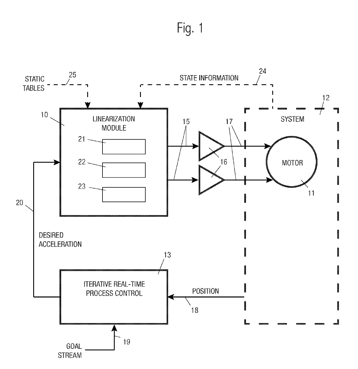
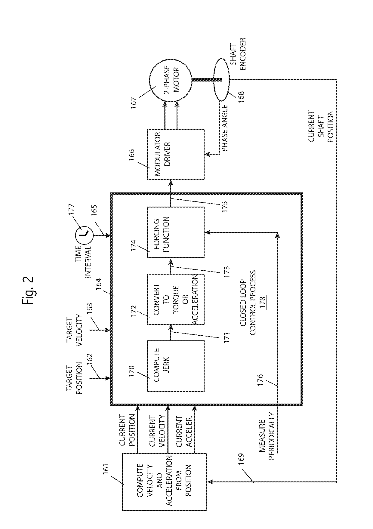
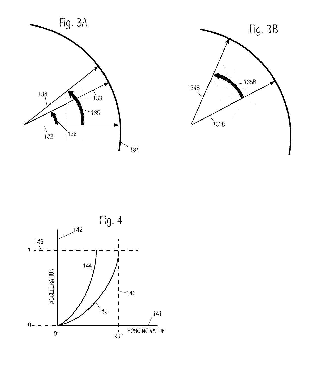
A device and method of iterative motion control is described using a non-linear table in a feedback loop to convert a desired acceleration input to motor drive outputs, where the motor is part of a controlled motion system. The table may be a two- or three-dimensional table additionally responsive to the current system state, such as shaft speed, position, or phase angle. The motor may be a two-coil stepper motor where the corrected non-linearity serves the purpose of maintaining desired toque. Inputs may be waypoints comprising both a target position and target velocity. The motion system may use an inverted SCARA arm. Up to three non-linear correction tables may be used: a first corrects motor steps to a more accurate shaft angle; a second corrects motor drive signals to achieve desired torque; a third correct motor drive signals responsive to shaft speed. Tables may be generated by a series of motion passes using a fixed shaft offset angle for each pass.

Description

[0001]This application claims priority to U.S. Provisional application 62 / 328,547, filing date 27 Apr. 2016; prior art includes, U.S. Pat. No. 5,770,829A, “Katz”; U.S. Pat. No. 9,041,337B2, “Tian”; US20130197688A “Egi”; and U.S. Pat. No. 4,769,583A, “Goor”.BACKGROUND OF THE INVENTION[0002]The field of this invention is closed-loop controllers, particularly for control loops to maintain, at least part of the time, a desired acceleration for a motor or other actuator.[0003]Prior art motion controller typically monitor a position and respond with changes in a drive signal to maintain a desired position, which may be relatively static or dynamic. Other prior art controllers monitor a velocity and respond with changes to a drive signal to maintain a desired velocity, typically static, although sometimes dynamic.[0004]A common feedback method is PID, or proportional-integration-differential, in which an error signal, and integrated error signal and a differentiated control signal are each...

Claims


Application Information

Patent Timeline
IPC IPC(8): G05B19/35
CPCG05B19/358G05B2219/41206G05B2219/41326G05B2219/42064G05B11/42G05B19/351G05B19/404G05B2219/41213H02P8/22H02P23/20G05B11/06G05B11/36G05B13/04G05B19/416
Inventor SKOGSRUD, SIMENBOE-WIEGAARD, THOMAS
Owner POLARWORKS AS
Learn More