
Amine-substituted naphthalene derivatives and organic light emitting diodes including the same

Inactive Publication Date: 2019-05-09
SFC CO LTD
View PDF0 Cites 6 Cited by
  • Summary
  • Abstract
  • Description
  • Claims
  • Application Information

AI Technical Summary

Benefits of technology

The present invention provides a material that improves the efficiency and lifespan of organic light emitting diodes (OLEDs). This material is placed between the hole transport layer and the light emitting layer. By using this compound, the hole transport from the hole transport layer to the light emitting layer is facilitated, resulting in higher luminous efficiency and longer lifetime of the OLED.

Problems solved by technology

A large difference in highest occupied molecular orbital (HOMO) energy level between a hole transport layer and a light emitting layer makes it difficult to transport holes from the hole transport layer to the light emitting layer, leading to the accumulation of holes at the interface between the hole transport layer and the light emitting layer.

Method used


Image

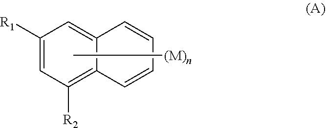
  • Amine-substituted naphthalene derivatives and organic light emitting diodes including the same
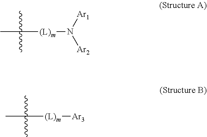
  • Amine-substituted naphthalene derivatives and organic light emitting diodes including the same
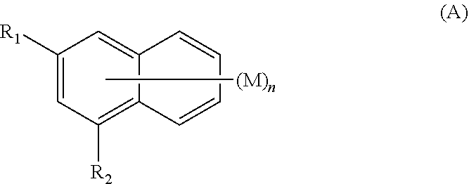
  • Amine-substituted naphthalene derivatives and organic light emitting diodes including the same

Examples


synthesis example 1

Synthesis of Compound 1

[0066](1) Synthesis Example 1-(1): Synthesis of Intermediate 1-a

[0067]335 g (1.5 mol) of 3-bromo-1-naphthol, 246 g (2.0 mol) of phenylboronic acid, 33.5 g (31.0 mmol) of tetrakis(triphenylphosphine)palladium, 430 g (3.1 mol) of potassium carbonate, 2 L of toluene, 2 L of 1,4-dioxane, and 1 L of water were refluxed in a round-bottom flask for 16 h. After completion of the reaction, the reaction mixture was left standing for layer separation. The organic layer was concentrated under reduced pressure and recrystallized from toluene and methanol to afford 330 g of Intermediate 1-a (yield 75%).

[0068](2) Synthesis Example 1-(2): Synthesis of Intermediate 1-b

[0069]20 g (0.091 mol) of Intermediate 1-a was placed in a round-bottom flask and 200 mL of dichloromethane was added thereto. The mixture was stirred. The mixture was added with 10.8 g (0.136 mol) of pyridine and was cooled to 0° C. After slow dropwise addition of 38.4 g (0.136 mol) of trifluoromethanesulfonic a...

synthesis example 2

Synthesis of Compound 7

[0073](1) Synthesis Example 2-(1): Synthesis of Intermediate 2-a

[0074]20 g (0.057 mol) of Intermediate 1-b, 21.6 g (0.085 mol) of bis(pinacolato)diborane, 1.2 g (0.002 mol) of [1,1′-bis(diphenylphosphino)ferrocene]palladium(II) dichloride, 16.7 g (0.17 mol) of potassium acetate, and 200 mL of toluene were added to a round-bottom flask under a nitrogen atmosphere. The mixture was refluxed. After completion of the reaction, the reaction mixture was left standing for layer separation. The organic layer was concentrated under reduced pressure, purified by column chromatography, and dried to afford 15 g of Intermediate 2-a (yield 80%)

[0075](2) Synthesis Example 2-(2): Synthesis of Intermediate 2-b

[0076]Intermediate 2-b was synthesized in the same manner as in Synthesis Example 1-(1), except that 1,4-bromoiodobenzene and Intermediate 2-a were used instead of 3-bromo-1-naphthol and phenylboronic acid, respectively.

[0077](3) Synthesis Example 2-(3): Synthesis of Compo...

synthesis example 3

Synthesis of Compound 14

[0080](1) Synthesis Example 3-(1): Synthesis of Intermediate 3-a

[0081]Intermediate 3-a was synthesized in the same manner as in Synthesis Example 1-(3), except that 4-aminobiphenyl was used instead of bis(biphenyl-4-yl)amine.

[0082](2) Synthesis Example 3-(2): Synthesis of Compound 14

[0083]Compound 14 was synthesized in the same manner as in Synthesis Example 2-(3), except that Intermediate 3-1 and 2-bromodibenzothiophene were used instead of Intermediate 2-b and bis(biphenyl-4-yl)amine, respectively.

[0084]MS (MALDI-TOF): m / z 533.19[M+]


PUM


Abstract

Disclosed are amine-substituted naphthalene derivatives and organic light emitting diodes including the same. In the organic light emitting diodes, at least one of the amine-substituted naphthalene derivatives is employed in a hole auxiliary layer interposed between a hole transport layer and a light emitting layer to enable efficient hole transport to the light emitting layer, achieving high luminous efficiency and long lifetime.

Description

CROSS REFERENCE TO RELATED APPLICATION(S)[0001]This application claims the benefit under 35 USC 119(a) of Korean Patent Application No. 10-2017-0148234 filed on Nov. 8, 2017 in the Korean Intellectual Property Office, the entire disclosure of which is incorporated herein by reference for all purposes.BACKGROUND OF THE INVENTION1. Field of the Invention[0002]The present invention relates to amine-substituted naphthalene derivatives and organic light emitting diodes including the same. More specifically, the present invention relates to organic light emitting diodes in which an amine-substituted naphthalene derivative is employed in a hole auxiliary layer interposed between a hole transport layer and a light emitting layer to enable efficient hole transport to the light emitting layer, achieving high luminous efficiency and long lifetime.2. Description of the Related Art[0003]Organic light emitting diodes are self-luminous devices in which electrons injected from an electron injecting...

Claims


Application Information

Patent Timeline
IPC IPC(8): H01L51/00C07C211/58
CPCH01L51/006C07C211/58H01L51/5088H01L51/5056H01L51/5008H01L51/5012H01L51/5072H01L51/5092C07D333/58C07D213/74C07D333/72C07C211/60C07C211/61C07D409/12C07D491/048C07D307/91H10K85/631H10K85/633H10K50/11H10K50/15H10K85/615H10K30/865H10K50/16H10K50/17H10K50/171
Inventor LEE, SE-JINLEE, BONG-HYANGYU, TAEJUNGCHOI, YEONGTAELEE, DAJUNG
Owner SFC CO LTD
Features
  • Generate Ideas
  • Intellectual Property
  • Life Sciences
  • Materials
  • Tech Scout
  • Unparalleled Data Quality
  • Higher Quality Content
  • 60% Fewer Hallucinations
Learn More