Heat transfer compositions, methods, and systems

a heat transfer composition and composition technology, applied in the field of heat transfer compositions, methods, systems, can solve the problems of increased environmental emissions, environmental protection, loss of refrigerant thermodynamic performance or energy efficiency, etc., and achieve excellent heat transfer properties and low or no toxicity

Active Publication Date: 2019-05-30
HONEYWELL INT INC
View PDF3 Cites 12 Cited by
  • Summary
  • Abstract
  • Description
  • Claims
  • Application Information

AI Technical Summary

Benefits of technology

[0014]Applicants have found that the compositions of the present invention satisfy in an exceptional and unexpected way the need for alternatives and/or replacements for and/or retrofits for refrigerants, in particular R-404A, in heat transfer applications in which has been commonly used. In particular the present invention provides heat transfer fluids, heat transfer methods and heat transfer systems that exhibit in preferred embodiments th...

Problems solved by technology

With regard to efficiency in use, it is important to note that a loss in refrigerant thermodynamic performance or energy efficiency may have secondary environmental impacts through increased fossil fuel usage arising from an increased demand for electrical energy.
In other words, a proposed new refrigerant that has an improved GWP and/or ODP relative to an existing fluid might nevertheless be less environmentally friendly than the fluid it is replacing if another characteristic of the proposed new fluid, such as efficiency in use, results in increased environmental emissions indirectly, such as by requiring higher fuel combustion to achieve ...

Method used


Image

  • Heat transfer compositions, methods, and systems
  • Heat transfer compositions, methods, and systems
  • Heat transfer compositions, methods, and systems

Examples


example 1

Vapor Injection Refrigeration System

[0925]The thermal stability of Refrigerant A2 was evaluated based on standard sealed tube testing according to ANSI / ASHRAE Standard 97-2007. Experimental results showed that the preferred discharge temperature is 135° C. or lower.

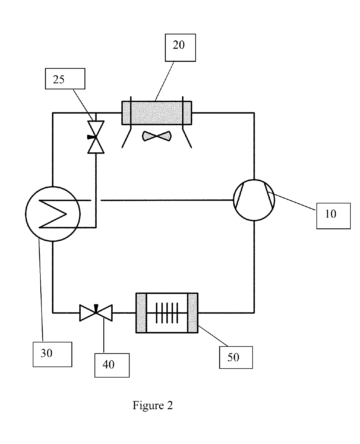
[0926]Variation of condensing temperatures due to changing ambient conditions affect the system performance and compressor discharge temperature. A refrigeration system containing a vapor injection and having a suction line heat exchanger was operated using a refrigerant consisting of composition A2 and with three different condensing temperatures, namely: 10° C., 32.2° C., 54.4° C. For each of these condenser temperatures, the system was run with substantially the same operating conditions / parameters as indicated below:

[0927]The vapor injection refrigeration system of the type illustrated generally in FIG. 2 hereof removes the vapor from a flash tank expansion device downsteam of the condenser. This vapor flow is injecte...

example 2

Liquid Injection Refrigeration System

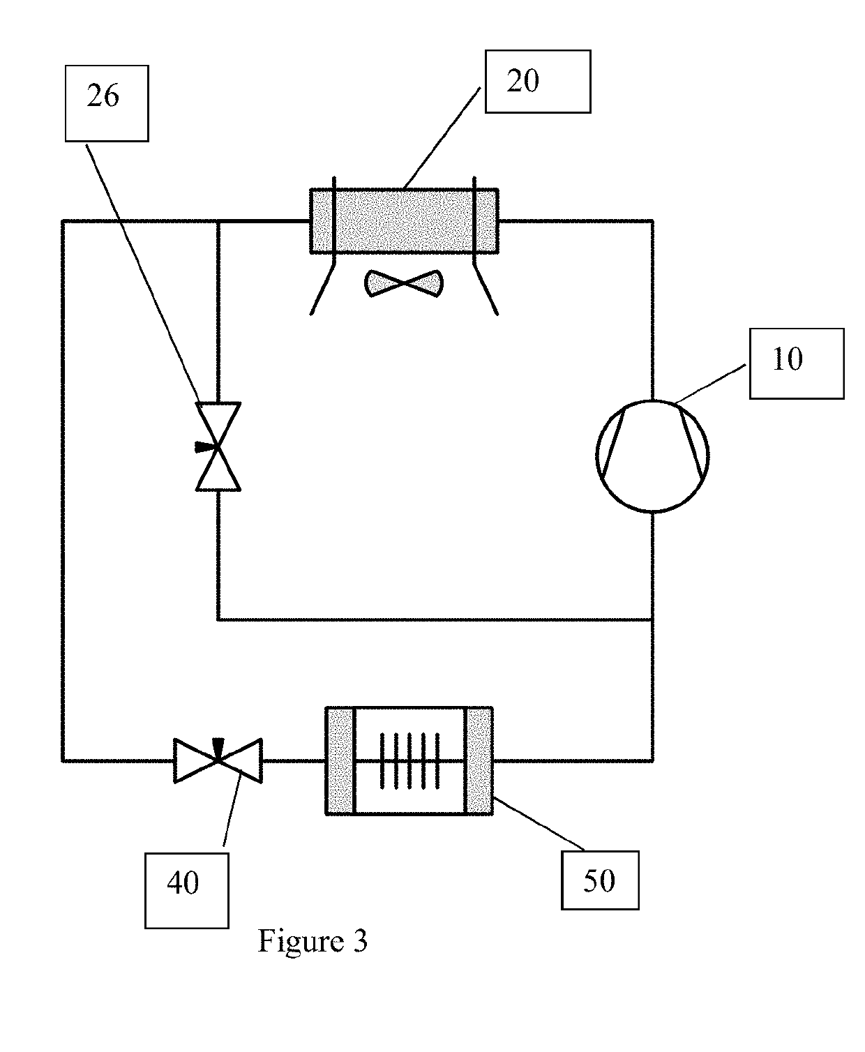
[0936]Refrigerant A2 was used for this Example. Variation of condensing temperatures due to changing ambient conditions affect the system performance and compressor discharge temperature. A liquid injection refrigeration system of the type illustrated generally in FIG. 3 injects liquid refrigerant after the condenser into a first compression stage of the compression process and reduces the compressor discharge temperature. For this example, different maximum compressor discharge temperatures were specified that require different amounts of injected refrigerant to maintain the maximum allowable discharge temperature. The target is efficiency within 5% of system without liquid injection.

[0937]Operating conditions were:

[0938]Condensing temperature=10 C, 32.2 C, 54.4 C;

[0939]Condenser sub-cooling=5.5° C.;

[0940]Evaporating temperature=−28.9° C.;

[0941]Evaporator Superheat=5.5° C.;

[0942]Isentropic Efficiency=65%;

[0943]Volumetric Efficiency=100%; Refrige...

example 3

Refrigeration System with Suction Line Heat Exchanger

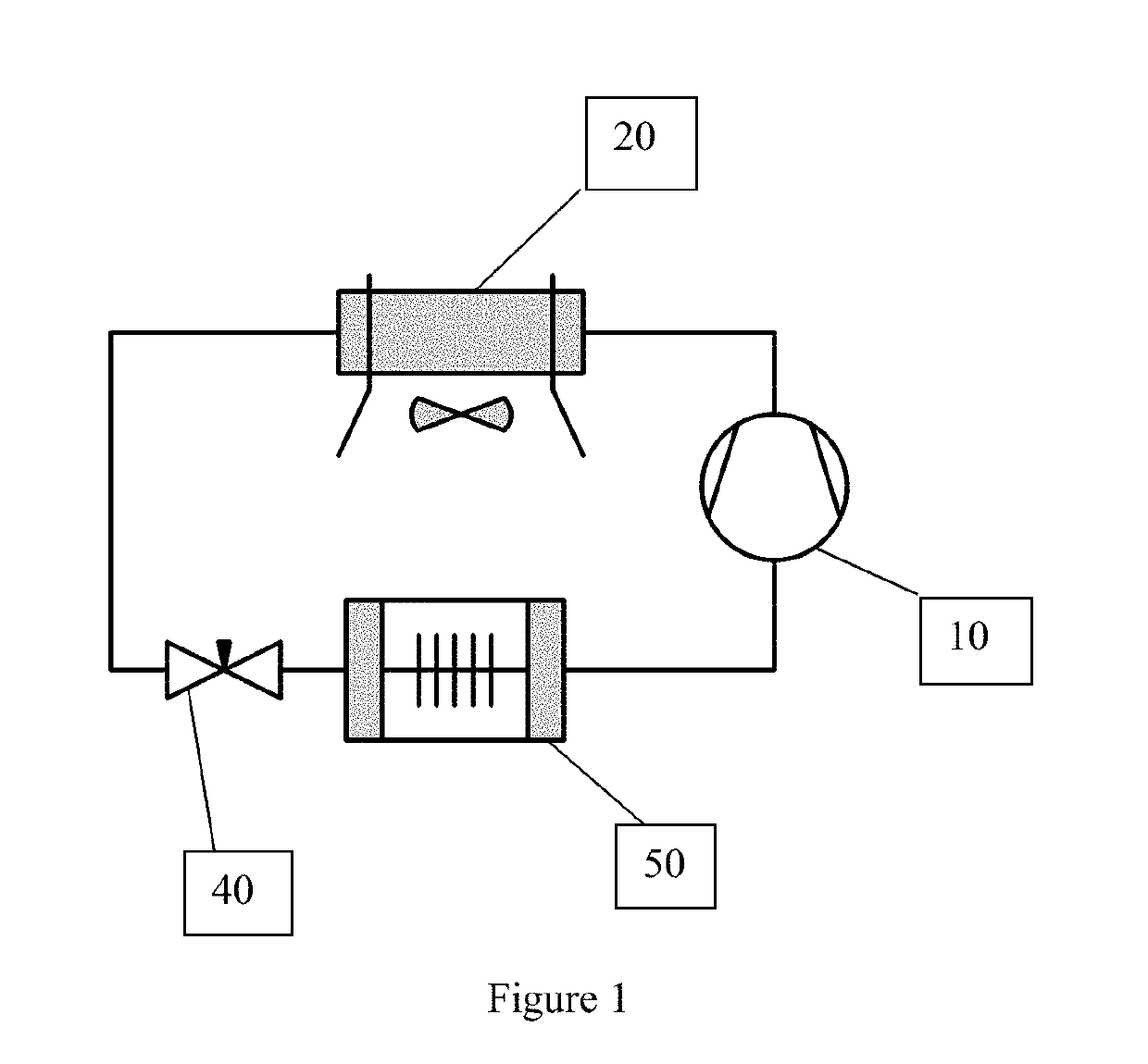
[0947]Refrigerant A2 was used for this Example. A suction line heat exchanger (hereinafter “SLHX”) used to transfer heat from the liquid line after the condenser to the vapor line after the evaporator as disclosed generally in FIG. 4 hereof. The use of a SLHX as per this example has several effects on the system performance. On the one hand, the temperature of the liquid after the condenser is reduced. Due to this, the inlet quality to the evaporator after the expansion process is reduced which at the same time leads to an increase in evaporator enthalpy difference effectively increasing the cooling capacity. On the other hand, the temperature of the vapor leaving the evaporator is increased which reduces the suction density and leads to an increase in compressor power consumption. Both effects need to be compared to determine if the overall effect is beneficial. This can vary based on the properties of each refrigerant tested. As...


PUM

PropertyMeasurementUnit
Temperatureaaaaaaaaaa

Abstract

The present invention relates to a refrigerant composition, including trifluoroiodomethane (CF3I); 1,1,1,2-tetrafluoropropene (HFO-1234yf); difluoromethane (HFC-32); and carbon dioxide (CO2), for use in a heat exchange system, including refrigeration applications and in particular aspects to the use of such compositions as a replacement of the refrigerant R-404A for heating and cooling applications and to retrofitting heat exchange systems, including systems designed for use with R-404A.

Description

CROSS REFERENCE TO RELATED APPLICATIONS[0001]This application claims priority to pending U.S. Ser. No. 62 / 587,722 filed on Nov. 17, 2017 incorporated herein in its entirety.[0002]This application claims priority to pending U.S. Ser. No. 62 / 592,494 filed on Nov. 30, 2017 incorporated herein in its entirety.[0003]The present application claims the priority benefit of U.S. Provisional 62 / 593,393, filed Dec. 1, 2017, which is incorporated herein by reference.FIELD OF THE INVENTION[0004]This invention relates to compositions, methods, and systems having utility in refrigeration applications, with particular benefit in medium and low temperature refrigeration applications, and in particular aspects to refrigerant compositions for replacement of the refrigerant R-404A for heating and cooling applications in medium and low temperature refrigerant systems, including systems designed for use with R-404A, and to retrofitting medium and low temperature refrigerant systems, including systems des...

Claims


Application Information

Patent Timeline
IPC IPC(8): C09K5/04C10M107/32F25B9/00
CPCC09K5/044C10M107/32F25B9/006C09K2205/122C09K2205/126C09K2205/106C10M2209/1023C10N2240/30F25B9/008F25B31/008F25B40/00F25B2400/121F25B2400/13C10M171/008C10M2203/065C10M2205/0265C10M2205/0285C10M2205/063C10M2207/2835C10N2020/097C10N2020/106C10N2020/101C09K5/045C09K2205/40F25J1/0097F25J1/0095C10N2040/30
Inventor YANA MOTTA, SAMUELPETERSENSETHI, ANKITVERA BECERRA, ELIZABETH DEL CARMENZOU, YANGSMITH, GREGORY
Owner HONEYWELL INT INC
Why Eureka
Try Eureka