

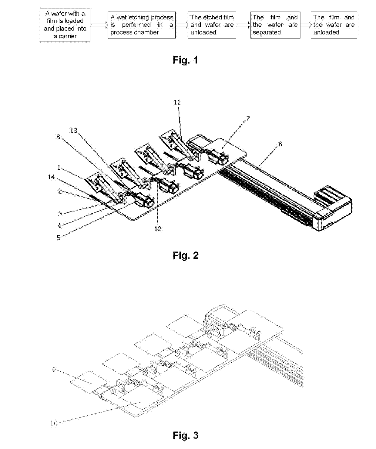
Independently-driven Film Separation Mechanism
a film separation and independent technology, applied in the field of solar cells, can solve the problems of low flexibility and fault tolerance of the entire system
- Summary
- Abstract
- Description
- Claims
- Application Information
AI Technical Summary
Benefits of technology
Problems solved by technology
Method used
Image

Examples
Embodiment Construction
[0030]The implementation manners of the present disclosure will be further described in detail below with reference to the accompanying drawings and embodiments. The following embodiments are used to illustrate the present disclosure, but are not used to limit the scope of the present disclosure.
[0031]In the description of the present disclosure, unless otherwise specified, “multiple” means two or more. The orientation or positional relationship indicated by the terms “up”, “down”, “left”, “right”, “inner”, “outer”, “front end”, “rear end”, “head”, “tail”, etc. is the orientation or positional relationship shown in the drawings, which is merely for the convenience of describing the present disclosure and simplifying the description, and does not indicate or imply that the referred device or element must have a specific orientation and must be constructed and operated in a specific orientation, and thus it cannot be construed as a limitation of the present disclosure. Moreover, the t...
PUM
 Abstract
Description
Claims
Application Information