Steel sheet

a technology of steel sheets and tensile steel, applied in the field of steel sheets, can solve the problems of deterioration of weldability, impaired formability of steel sheets, and often subjected steel sheets to welding, and achieve excellent weldability, tensile strength and uniform elongation, and high tensile strength

Inactive Publication Date: 2019-07-11
NIPPON STEEL CORP
View PDF1 Cites 5 Cited by
  • Summary
  • Abstract
  • Description
  • Claims
  • Application Information

AI Technical Summary

Benefits of technology

[0021]In the steel sheet according to the aspect of the present invention, since the C content is 0.40 mass % or less, the steel sheet has excellent weldability. In addition, in the steel sheet according to the present invention, the product “TS×uEL” of tensile strength and uniform elongation is high. This means that both tensile strength and uniform elongation which are properties being contrary to each other are excellent. Moreover, in the steel sheet according to the present invention, the product “TS×λ” of tensile strength and hole expansibility is high. This means that both tensile strength and hole expansibility which are properties being contrary to each other are excellent.
[0022]According to the present invention, it is possible to provide a high strength steel sheet having more excellent tensile strength, uniform elongation, and hole expansibility than those in a technology in the related art, with a smaller C content than that in the technology in the related art. Particularly, both weight reduction and safety of vehicles can be enhanced and easy welding can also be ensured by using this steel sheet. Thus, industrial contribution is extremely remarkable.

Problems solved by technology

Generally, if a steel sheet is highly strengthened, uniform elongation, hole expansibility, and the like are degraded, so that formability of the steel sheet is impaired.
However, in a case where a steel sheet is used in a structural member, the steel sheet is often subjected to welding.
If a C content is in a steel sheet, it leads to deterioration in weldability, so that the steel sheet is limited in being used as a structural member.
However, in a case where bainite having low ductility is used as a main structure, ductility of a steel sheet is degraded, so that it is difficult to produce vehicle members having a complicated shape.
However, there are few examples for this kind of steel being intended to be applied to members for vehicles, and improvement in hole expansibility has not been sufficiently examined.
However, the steel sheet disclosed in Patent Document 4 is a DP steel having an excellent r value, but the steel sheet is not excellent in strength and ductility.
Steel sheets having such a structure do not exhibit all of tensile strength, ductility, and hole expansibility required in steel sheets for vehicles.

Method used


Image

  • Steel sheet
  • Steel sheet

Examples


example 1

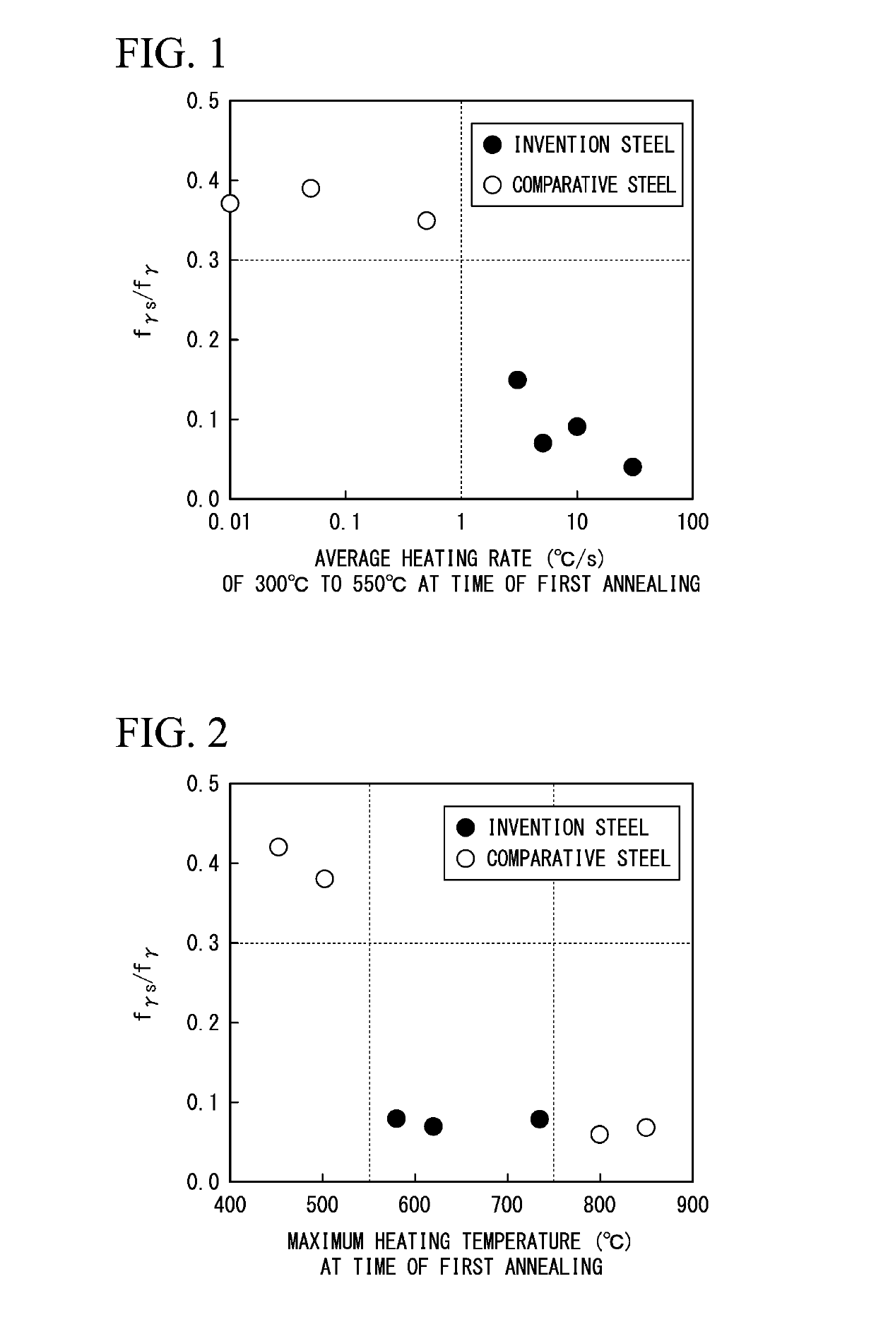
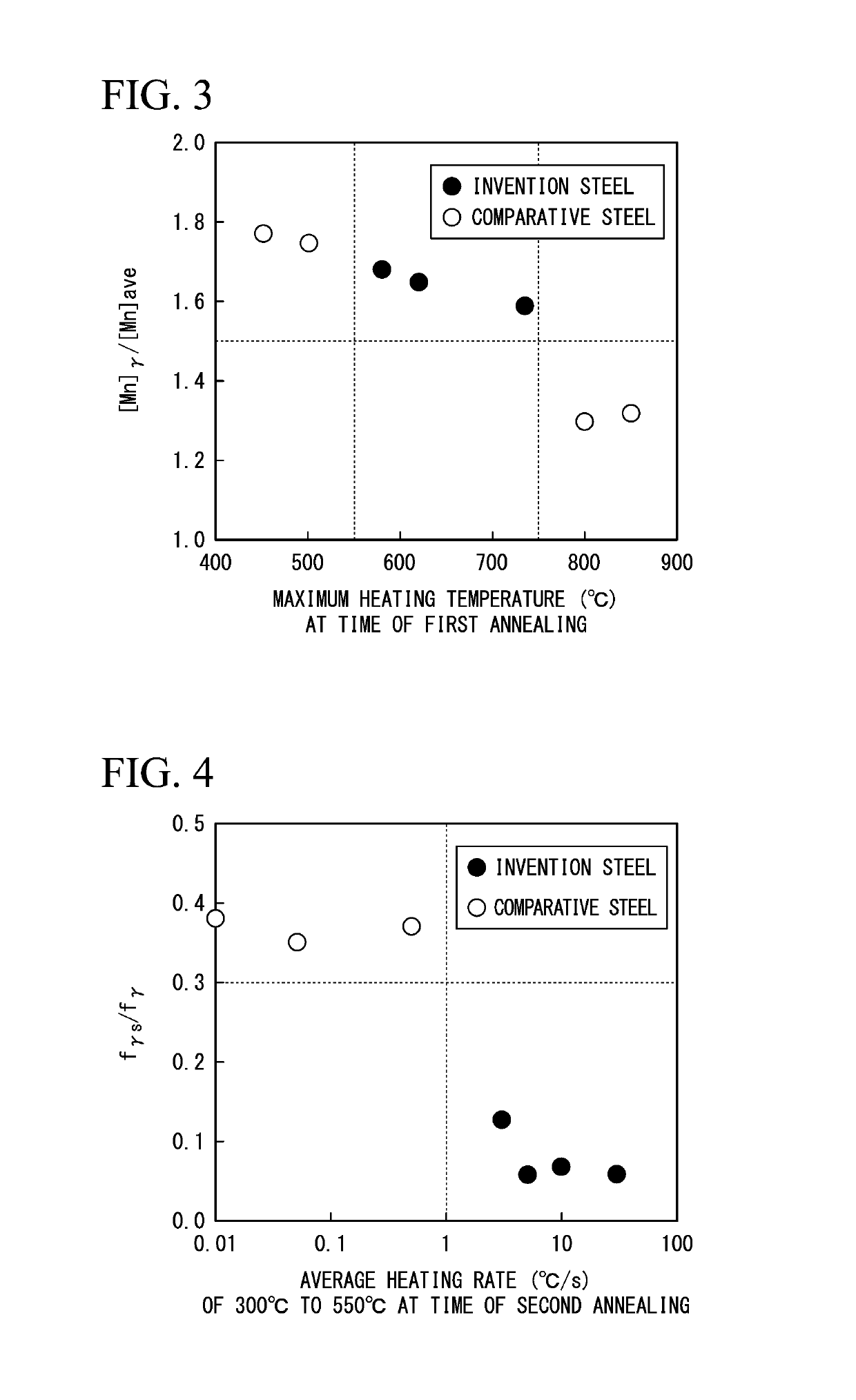
[0137]First, in order to investigate the influence of the heating rate in the first annealing, an experiment was performed as described below.

[0138]A slab having the chemical composition, by unit mass %, consisting of C: 0.10%, Si: 1.0%, Mn: 4.3%, P: 0.010%, S: 0.0020%, Al: 0.03%, N: 0.0020%, O: 0.0012%, and the remainder was Fe and impurities was produced by using a vacuum melting furnace. The obtained slab was heated to 1,200° C. and was subjected to hot rolling at the finishing temperature of 921° C. Thereafter, the slab was cooled at the average cooling rate set to 50° C. / s within the temperature range from 800° C. to the coiling start temperature and was wound at 450° C. After the wound hot rolled steel sheet was cooled to room temperature, the first annealing was performed. In heating before the first annealing, the average heating rate within the temperature range of 300° C. to 550° C. was set to various values within a range of 0.01° C. / s to 30° C. / s. The annealing temperatu...

example 2

[0142]Next, in order to investigate the influence of the annealing temperature in the first annealing, an experiment was performed as described below.

[0143]The slab used in Example 1 was heated to 1,200° C. and was subjected to hot rolling at the finishing temperature of 921° C. Thereafter, the slab was cooled at the average cooling rate of 50° C. / s within the temperature range from 800° C. to the coiling start temperature, and coiling treatment was performed at 450° C. After the wound hot rolled steel sheet was cooled to room temperature, the first annealing was performed. The average heating rate within the range of 300° C. to 550° C. before the first annealing (in a case where the annealing temperature was less than 550° C., within the range from 300° C. to the annealing temperature) was set to 3.5° C. / s. Subsequently, heating of each of the samples ended at 450° C. to 850° C. Thereafter, each of the samples was retained at each annealing temperature for 7,200 seconds, and then e...

example 3

[0145]Next, in order to investigate the influence of the heating rate in the second annealing, an experiment was performed as described below.

[0146]The slab used in Example 1 was heated to 1,200° C. and was subjected to hot rolling at the finishing temperature of 921° C. Thereafter, the slab was cooled at the average cooling rate set to 50° C. / s within the section from 800° C. to the coiling start temperature, and coiling treatment was performed at 450° C. Thereafter, in the first annealing, each of the samples was heated at the average heating rate of 2.5° C. / s within the range of 300° C. to 550° C., and each of the samples was retained at 590° C. for 7,200 seconds. Then, each of the samples was cooled to room temperature by air cooling. Thereafter, cold rolling at a cold rolling reduction of 52% was performed for each of the samples. Then, each of the samples was heated the average heating rate of 0.01° C. / sec to 30° C. / sec within the range of 300° C. to 550° C. Moreover, after ea...


PUM

PropertyMeasurementUnit
aspect ratioaaaaaaaaaa
metallographic structureaaaaaaaaaa
concentrationaaaaaaaaaa

Abstract

A steel sheet according to an aspect of the present invention includes a predetermined chemical composition; in which a metallographic structure in a ¼ t portion contains residual austenite of 4 volume % to 70 volume %; [Mn]γ/[Mn]ave>1.5 is satisfied in the ¼ t portion; fγs/fγ≤0.30 and [C]×[Mn]≥0.15 are satisfied in the ¼ t portion.

Description

TECHNICAL FIELD OF THE INVENTION[0001]The present invention relates to a steel sheet having excellent formability, that is, excellent uniform elongation, excellent weldability, and high strength.RELATED ART[0002]In order to achieve both weight reduction and safety in vehicle bodies, components, and the like of vehicles, high-strengthening of steel sheets used as materials thereof has been in progress. Generally, if a steel sheet is highly strengthened, uniform elongation, hole expansibility, and the like are degraded, so that formability of the steel sheet is impaired. Therefore, in order to use high strength steel sheets as members for vehicles, both strength and formability, which are properties being contrary to each other, are required to be enhanced.[0003]In order to improve uniform elongation, a so-called TRIP steel sheet utilizing transformation induced plasticity of residual austenite (residual γ) is proposed at present (for example, refer to Patent Documents 1 and 2).[0004]...

Claims


Application Information

Patent Timeline
Patent Type & Authority Applications(United States)
IPC IPC(8): C22C38/04C22C38/06C22C38/02C22C38/00C22C38/60C22C38/20C22C38/22C22C38/12C22C38/08C22C38/14C22C38/38C23C2/02C23C2/06C23C2/40
CPCC22C38/04C22C38/06C22C38/02C22C38/001C22C38/002C22C38/005C22C38/008C22C38/60C22C38/20C22C38/22C22C38/12C22C38/08C22C38/14C22C38/38C23C2/02C23C2/06C23C2/40C21D2211/001C21D8/0263C21D8/0226C21D8/0236C21D8/0205C21D9/46C22C38/58C21D9/48C21D6/008C21D6/005C21D1/26C21D6/001C21D6/002C21D8/0436C21D8/0426C21D8/0463C22C38/34C23C2/28C23C2/024C23C2/0224
Inventor SANO, KOHICHIAZUMA, MASAFUMISAKAKIBARA, MUTSUMIUENISHI, AKIHIROHAYASHI, KOUTAROU
Owner NIPPON STEEL CORP
Why Eureka
Try Eureka