
Automated Cryogenic Refilling System

a refilling system and automatic technology, applied in the direction of container filling under pressure, instrumentation, container discharging methods, etc., can solve the problems of time-consuming and difficult to fill cryostats with liquid helium from one or more helium dewars, and achieve the effect of preventing the build-up of pressur

Active Publication Date: 2019-07-11
UT BATTELLE LLC
View PDF0 Cites 4 Cited by
  • Summary
  • Abstract
  • Description
  • Claims
  • Application Information

AI Technical Summary

Benefits of technology

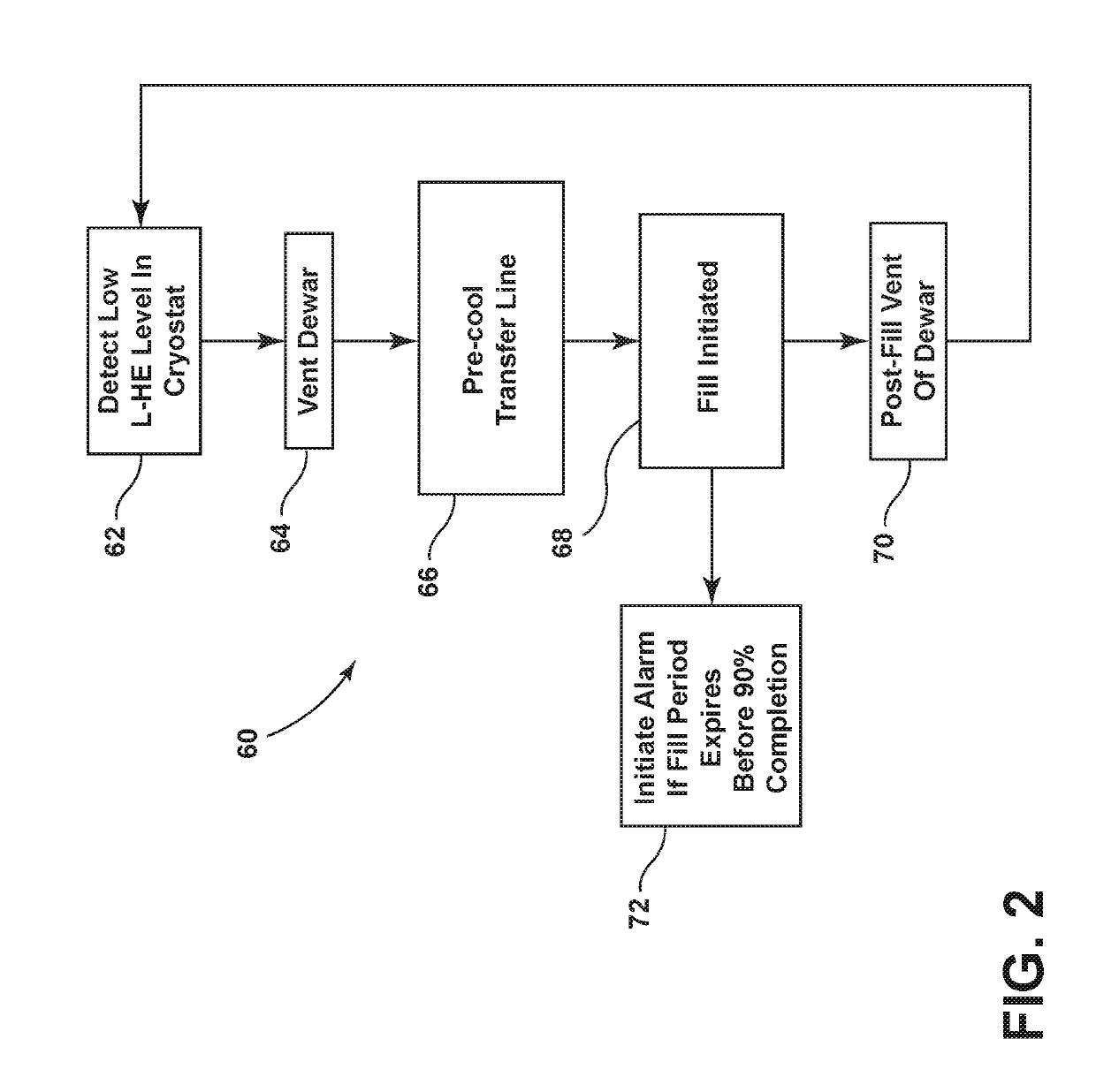
The patent text describes a method for refueling a cryostat with helium. The system automates the process, which helps to minimize helium losses during filling and reduces the risk of contamination. The method involves venting gaseous helium from a dewar and pre-cooling a transfer line, then feeding the gaseous helium to the dewar to force the liquid helium through the pre-cooled transfer line and into the cryostat. The system also includes a level sensor to stop the flow of gaseous helium when the level of liquid helium in the cryostat reaches a predetermined level. Additionally, the method includes venting gaseous helium from the dewar to prevent the build-up of pressure while the transfer line remains connected. Overall, the system and method described in the patent make the refueling process more efficient and reliable.

Problems solved by technology

In practice, it is often difficult and time consuming to fill cryostats with liquid helium from one or more helium dewars.
Filling with liquid helium can be a challenge, from filling every day or twice a day depending on the type of cryostat or magnets.

Method used


Image

  • Automated Cryogenic Refilling System
  • Automated Cryogenic Refilling System

Examples


Embodiment Construction

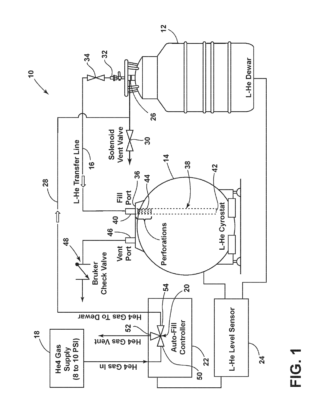
[0012]An automated cryogenic refilling system in accordance with a current embodiment is illustrated in FIG. 1 and generally designated 10. The system 10 generally includes a dewar 12 containing liquid helium, a helium storage cryostat 14 in fluid communication with the dewar 12 through a liquid helium transfer line 16, and a source of gaseous helium 18 in fluid communication with the dewar 12 through a three-position electronic fill valve 20. The fill valve 20 is responsive to a controller 22 coupled to the output of a liquid level meter 24 to automatically refill the liquid level within the helium storage cryostat 14 with minimal helium losses. A system overview is discussed below, followed by a discussion of its method of operation and a laboratory example.

I. System Overview

[0013]As shown in FIG. 1, the dewar 12 includes a first port 26 in fluid communication with a gas transfer line 28 and a solenoid vent valve 30. The gas transfer line 28 transfers a push gas, for example gaseo...


PUM


Abstract

An improved system and method for the automated refilling of cryogenic helium is provided. In one embodiment, the system includes a dewar in fluid communication with a liquid helium cryostat through a cryogen transfer line. A controller regulates operation of a three-way valve to pre-cool the transfer line and to cause gaseous helium to flow to the dewar and force liquid helium through the transfer line into the cryostat. The controller is coupled to the output of a cryogenic level sensor, such that the controller regulates the helium liquid level within the cryostat. During filling cycles, the dewar liquid level is also monitored by the cryogenic level sensor and an alarm sounds if the dewar liquid level is undesirably low. Between filling cycles, the controller is operable to ventilate the dewar through a solenoid vent valve in fixed time intervals to ensure the dewar pressure is sufficiently low so as to not bleed liquid helium into the cryostat.

Description

CROSS-REFERENCE TO RELATED APPLICATION[0001]This application claims the benefit of U.S. Provisional Application 62 / 614,555, filed Jan. 8, 2018, the disclosure of which is hereby incorporated by reference in its entirety.STATEMENT REGARDING FEDERALLY SPONSORED RESEARCH AND DEVELOPMENT[0002]This invention was made with government support under Contract No. DE-AC05-00OR22725 awarded by the U.S. Department of Energy. The government has certain rights in the invention.BACKGROUND OF THE INVENTION[0003]The present invention relates to automated refilling systems for cryogenic helium and other liquids, optionally for use with superconducting magnet systems.[0004]Cryogenic liquids, including helium and nitrogen, are used in operations where superconductive magnets are required, for example in magnetic resonance imaging and nuclear magnetic resonance. Cryogenic liquids have boiling points much lower than room temperature (−452° F. and −320° F., respectively) and are typically stored in a cryo...

Claims


Application Information

Patent Timeline
IPC IPC(8): F17C5/06F17C13/02
CPCF17C5/06F17C13/025F17C2223/0161F17C2223/033F17C2221/017F17C2250/043F17C2225/0123F17C2203/0391F17C2250/032F17C2205/0335F17C2250/0417F17C2201/056F17C2205/0332F17C2225/044F17C2225/047F17C2201/0109F17C2225/033F17C2225/0161F17C2201/032F17C5/04F17C2250/0495F17C2250/0636F17C2250/077F17C2260/031F17C2260/02F17C2265/031F17C2270/0509F17C2270/0536G01R33/3815G01R33/3804
Inventor RUIZ-RODRIGUEZ, MARIANO MELORFI, SAAD RREDMON, CHRISTOPHER MMORGAN, RYAN J
Owner UT BATTELLE LLC
Learn More