Methods and apparatus to deliver therapeutic, non-ultraviolet electromagnetic radiation versatilely via a catheter residing in a body cavity

a technology of electromagnetic radiation and catheters, applied in the field of methods, can solve the problems of high morbidity and mortality rate, low efficacy of current methods of reducing or eliminating the number of infectious agents in, around, catheters

Active Publication Date: 2019-07-18
LIGHT LINE MEDICAL INC
View PDF0 Cites 6 Cited by
  • Summary
  • Abstract
  • Description
  • Claims
  • Application Information

AI Technical Summary

Benefits of technology

[0018]In some exemplary embodiments, methods and apparatuses are provided for effectively sterilizing a catheter and the area surrounding the catheter while the catheter is disposed in a body cavity. Such medical device assemblies use sterilizing EMR to reduce or eliminate the count of infectious agents in, on, or around the catheter and / or on or in tissue surrounding the catheter while in a body cavity.
[0027]A method for constructing an exemplary medical device assembly for insertion into a cavity of a patient's body and for delivery of a fluid to or retrieval from the patient's body may comprise the steps of: providing a catheter having an elongate catheter body with one or more internal lumens, a coupling end and an distal end, the distal end being insertable into the cavity of the patient's body; applying one or more optical elements within one or more lumens of the catheter body and / or within a wall of the catheter body, the optical element being conducive to the axial propagation of therapeutic EMR relative to the catheter body; and coupling at least one EMR source to the EMR conduction system and / or the catheter body, the EMR source for providing non-ultraviolet, therapeutic EMR having an intensity sufficient to inactivate one or more infectious agent and / or to enhance healthy cell growth.
[0030]At least one coupling connects the radiation source to the EMR conduction system and, in some exemplary embodiments, may comprise at least one feature that allows for the coupling to be readily removable from the EMR conduction system. The exemplary coupling may be achieved by utilizing a uniquely designed connection, a pre-manufactured coupling system, or any combination thereof that optimizes the coupling efficiency and utility. Further, such couplings couple the removably insertable EMR conduction system to the EMR source and may comprise more than one coupling with an intermediate section optimized to further the propagation of the EMR. In one exemplary embodiment, the EMR source may be coupled to a patch cable or EMR conduction extending segment, which is then coupled to the formal removably insertable EMR conduction system.
[0040]Still another exemplary embodiment achieves a gradient radial transmission wherein at least one portion of the optical fiber emits EMR radially in a gradient distribution. The gradient distribution may also be accomplished through chemical etching, physical etching, plasma or laser ablation in a uniform or gradient pattern. By altering at least one of velocity, acceleration, pressure gradients, flow, modification time, or modification material or process, it is possible to achieve a gradient radial transmission throughout a portion of the optical fiber. This may also be achieved through addition of microscopic structures positioned within the core and / or core-cladding boundary. Gradient radial transmission enables another exemplary embodiment to exhibit controlled relative intensity that may be uniform over a portion of the length and / or non-uniform and varying as desired.
[0043]Samples retrieved through the distal end are often used to characterize the type of infection. One exemplary embodiment of the disclosure focuses on maintaining axial propagation of the light relative to the catheter and delivering therapeutic light of sufficient intensity to the distal end of the catheter to reduce or eliminate the count of infectious agents residing thereon.

Problems solved by technology

These devices frequently give rise to infections caused by growth of infectious agents in, on, and around the catheter and on tissue surrounding the catheter.
Catheter related infections (CRIs) are a large problem in medicine, leading to high morbidity and mortality rates.
Current methods of reducing or eliminating the number of infectious agents in, on, around a catheter are of low efficacy.
Typically, catheters will be removed if they are suspected to be harboring infectious agents, increasing both the cost associated with treatment and patient discomfort.
Despite these techniques, infections resulting from catheters remain a major problem.
These infections, along with urinary tract infections, gastrointestinal infections, and other infections from catheters, increase both medical costs and patient discomfort.
Consequently, with smaller diameter catheters, there may be inadequate thickness to the catheter wall to carry a sterilization and / or healthy growth enhancing delivery system.
Unfortunately, UV light is well known to cause damage to living cells.
Methods to disinfect connectors, stopcocks, and valves using sterilizing electromagnetic radiation (EMR) have also been attempted using 405 nm light to sterilize these points, but these methods neglect disinfection of the catheter body as well as the tip of the catheter.
This biofilm facilitates the growth of infectious agents and is very difficult to break down once it has begun to grow.
The mechanism proposed by the team suggests that light in this range leads to photosensitization of endogenous porphyrins within the bacteria, which causes the creation of singlet oxygen, leading to the death of the bacteria.
Heretofore, however, there has never been apparatus or methods for making or using such apparatus to safely and effectively disinfect a catheter while it is still implanted in a patient.

Method used


Image

  • Methods and apparatus to deliver therapeutic, non-ultraviolet electromagnetic radiation versatilely via  a catheter residing in a body cavity
  • Methods and apparatus to deliver therapeutic, non-ultraviolet electromagnetic radiation versatilely via  a catheter residing in a body cavity
  • Methods and apparatus to deliver therapeutic, non-ultraviolet electromagnetic radiation versatilely via  a catheter residing in a body cavity

Examples


Embodiment Construction

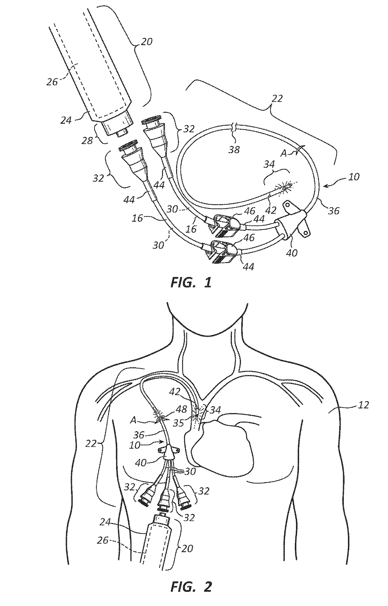
[0083]Exemplary embodiments of the present disclosure will be best understood by reference to the drawings, wherein like parts are designated by like numerals throughout. It will be readily understood that the components of the exemplary embodiments, as generally described and illustrated in the Figures herein, could be arranged and designed in a wide variety of different configurations. Thus, the following more detailed description of the exemplary embodiments of the apparatus, system, and method of the present disclosure, as represented in FIGS. 1 through 18B, is not intended to limit the scope of the invention, as claimed, but is merely representative of exemplary embodiments.

[0084]The phrases “attached to”, “secured to”, and “mounted to” refer to a form of mechanical coupling that restricts relative translation or rotation between the attached, secured, or mounted objects, respectively. The phrase “slidably attached to” refers to a form of mechanical coupling that permits relati...


PUM

PropertyMeasurementUnit
wavelengthsaaaaaaaaaa

Abstract

Methods and apparatus provide therapeutic electromagnetic radiation (EMR) for inactivating infectious agents in, on or around a catheter residing in a patient's body cavity and / or for enhancing healthy cell growth. Transmitting non-ultraviolet therapeutic EMR substantially axially along an optical element in a lumen of the catheter body and / or the catheter body. Through delivery of the therapeutic EMR to particular infected areas and / or areas requiring tissue healing. The inactivation of the major sources of infection in, on, and around catheters and / or enhance healthy cell growth around catheters is accomplished by utilizing controlled relative intensity and / or treatment region specific dosing of the therapeutic EMR emitted radially from the optical element. Specific embodiments of urinary catheters and peritoneal dialysis catheters are also disclosed.

Description

RELATED APPLICATIONS[0001]This application is a continuation-in-part of U.S. patent application Ser. No. 15 / 668,266, filed on Aug. 3, 2017 and entitled METHODS AND APPARATUS TO DELIVER THERAPEUTIC, NON-ULTRAVIOLET ELECTROMAGNETIC RADIATION TO INACTIVATE INFECTIOUS AGENTS AND / OR TO ENHANCE HEALTHY CELL GROWTH VIA A CATHETER RESIDING IN A BODY CAVITY (hereinafter the “Parent Application”), which is a continuation-in-part of U.S. patent application Ser. No. 13 / 801,750, filed on Mar. 13, 2013 and entitled METHODS AND APPARATUS TO INACTIVATE INFECTIOUS AGENTS ON A CATHETER RESIDING IN A BODY CAVITY, now issued as U.S. Pat. No. 9,808,647 on Nov. 7, 2017, which claimed the benefit of U.S. Provisional Application No. 61 / 686,432 filed Apr. 5, 2012 and was entitled HINS LASER LIGHT CATHETER. The Parent Application is also a continuation-in-part of U.S. application Ser. No. 15 / 424,732, filed Feb. 3, 2017 and entitled METHOD AND APPARATUS FOR REMOVABLE CATHETER VISUAL LIGHT THERAPEUTIC SYSTEM. ...

Claims


Application Information

Patent Timeline
Patent Type & Authority Applications(United States)
IPC IPC(8): A61N5/06A61L2/08A61M25/00A61L2/00
CPCA61N5/0601A61N5/0624A61L2/084A61L2/085A61M25/0028A61L2/0047A61L2202/24A61L2/0052A61L2/0058A61M2025/0037
Inventor BARNECK, MITCHELL D.RHODES, NATHANIEL L.R.ALLEN, JAMES P.LONG, CURTIS D.
Owner LIGHT LINE MEDICAL INC
Why Eureka
Try Eureka