
Temperature Feedback for Electro-optic Phase-shifters

a technology temperature feedback, which is applied in the direction of optical radiation measurement, instruments, heat measurement, etc., can solve the problems of significant compromise of camera or lidar performance, ambient temperature variation can disturb the accuracy and affect the performance of electro-optic phase shifters

Active Publication Date: 2019-07-25
ROBERT BOSCH GMBH
View PDF0 Cites 6 Cited by
  • Summary
  • Abstract
  • Description
  • Claims
  • Application Information

AI Technical Summary

Benefits of technology

The patent is about a way to account for changes in temperature in an optical device using electro-optic phase-shifters. The method involves integrating a temperature measurement component into the chip that controls the refractive index of the waveguide. This allows for temperature measurement without interfering with the phase shifting function. The technical effect is to improve the reliability and stability of optical devices that use phase-shifters.

Problems solved by technology

However, the performance of electro-optic phase-shifters can be affected at temperatures outside a preferred operating range because the voltage required to induce a desired phase shift is typical temperature dependent.
Thus, depending on the material and the structure of the phase-shifters, ambient temperature variation can disturb the accuracy of an electro-optic phase-shifter.
Any minor deviation in the voltage required for a desired phase shift due to temperature can significantly compromise the performance of the camera or Lidar unless the applied voltage is adjusted.

Method used


Image

  • Temperature Feedback for Electro-optic Phase-shifters
  • Temperature Feedback for Electro-optic Phase-shifters
  • Temperature Feedback for Electro-optic Phase-shifters

Examples


Embodiment Construction

[0009]For the purposes of promoting an understanding of the principles of the disclosure, reference will now be made to the embodiments illustrated in the drawings and described in the following written specification. It is understood that no limitation to the scope of the disclosure is thereby intended. It is further understood that the present disclosure includes any alterations and modifications to the illustrated embodiments and includes further applications of the principles disclosed herein as would normally occur to one skilled in the art to which this disclosure pertains.

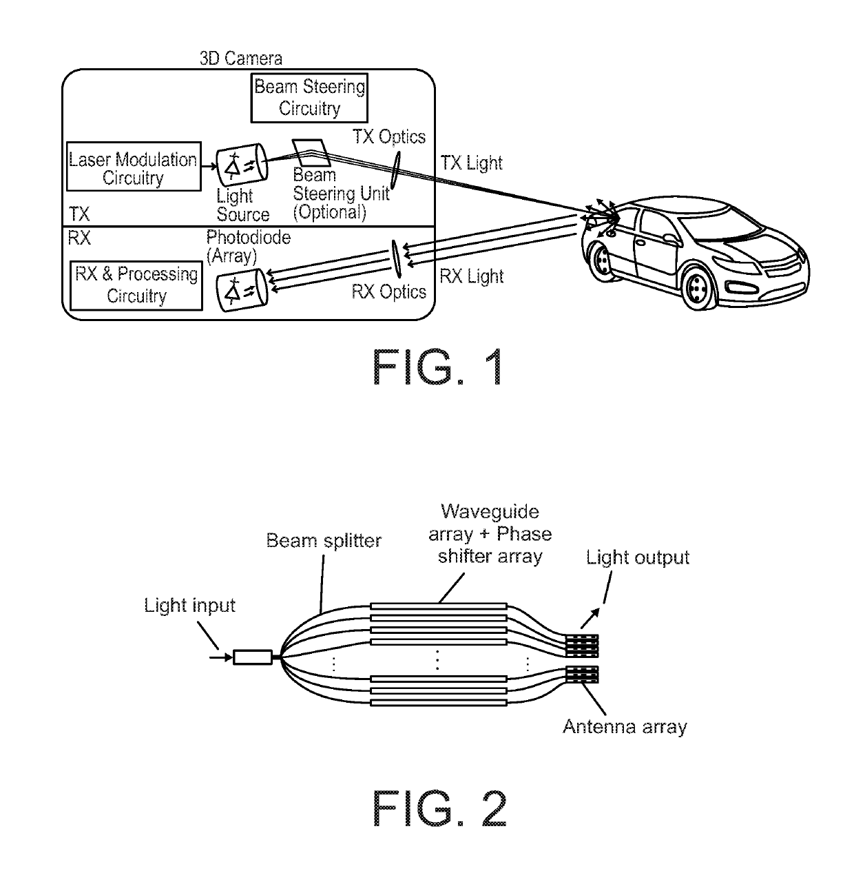
[0010]The general architecture of a Lidar system or a 3D camera is shown in FIG. 1. The 3D camera includes a transmitter TX operable to modulate the amplitude of the light from a light source, such as a laser, into a series of pulses, in which the light is distributed to a scene using proper optical elements. The camera further includes a receiver RX in which the reflected light from the scene is collected a...


PUM

PropertyMeasurementUnit
refractive indexaaaaaaaaaa
temperatureaaaaaaaaaa
voltageaaaaaaaaaa

Abstract

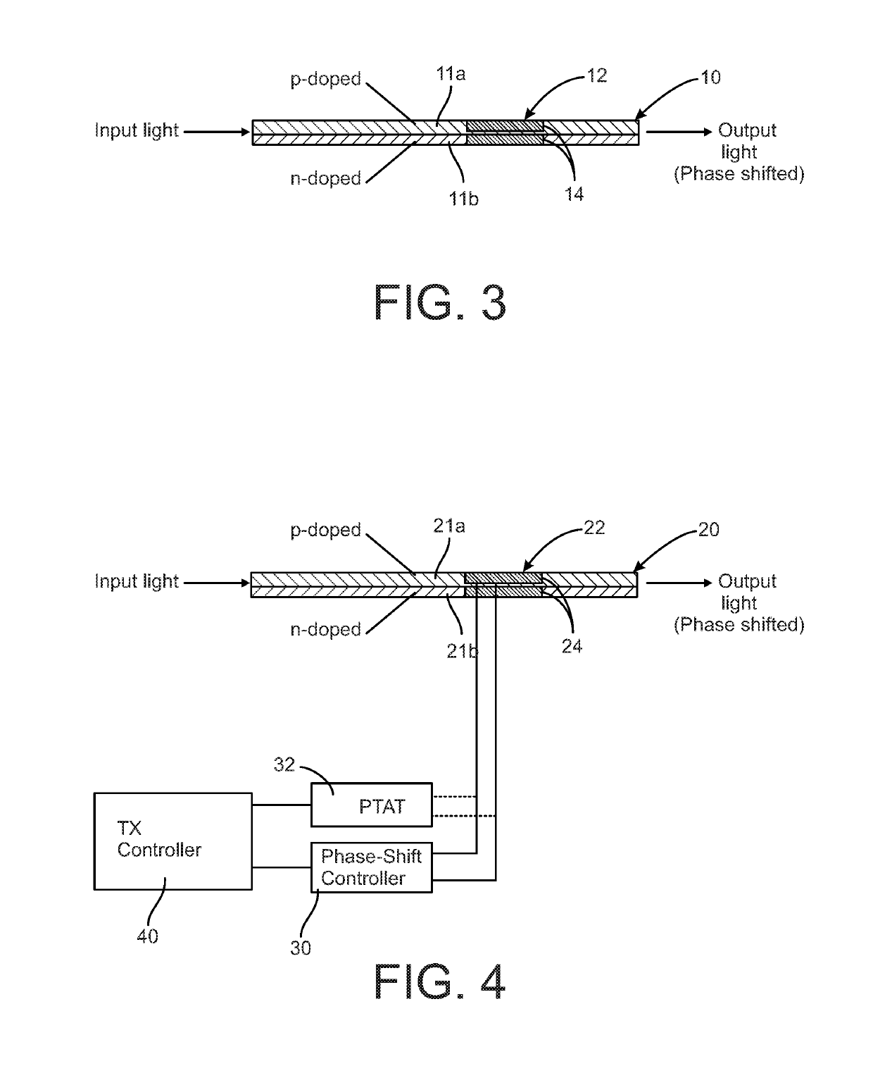
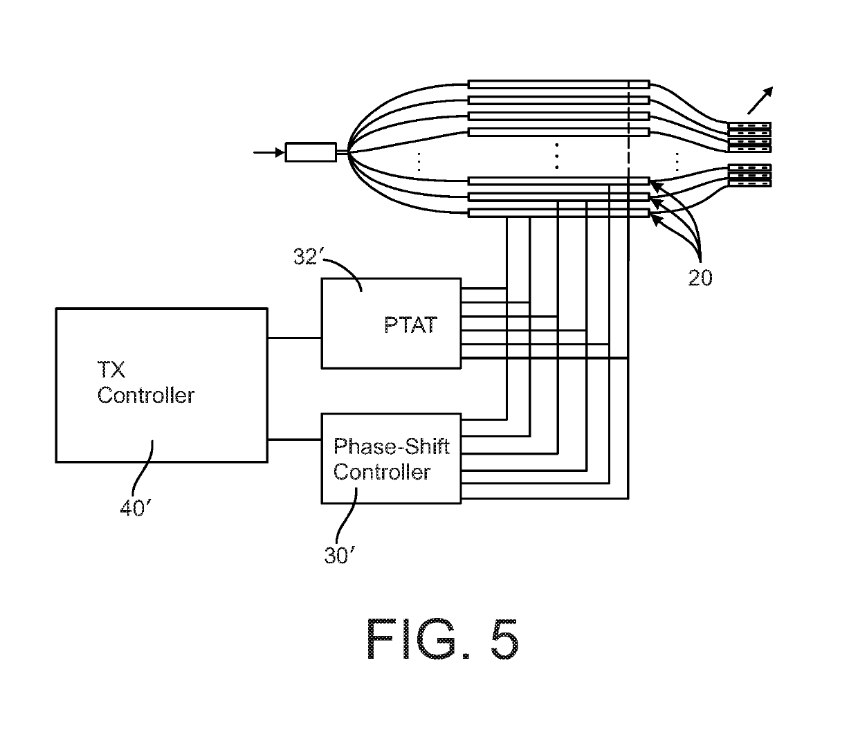
A transmitter for an optical device includes semi-conductor waveguides, each incorporating an electro-optic phase-shifter in the semi-conductor waveguide that is operable to change the refractive index of the waveguide to thereby introduce a phase shift in the light propagated through the waveguide. The electro-optic is connected to a phase shift controller and to a temperature measurement component, such as a PTAT circuit, that is integrated into the electronic or photonic chip carrying the waveguide. Temperature measurement by the measurement component can be multiplexed with the normal operation of the phase-shifter so that the temperature measurement function does not interfere with the phase shifting function.

Description

PRIORITY CLAIM[0001]This application is utility filing from and claims priority to U.S. Provisional Application No. 62 / 619,156, filed on Jan. 19, 2018, the entire disclosure of which is incorporated herein by reference.BACKGROUND[0002]For optical phased-arrays (OPAs), electro-optic phase-shifters are preferred for their performance metrics, such as lower power consumption and high speed. However, the performance of electro-optic phase-shifters can be affected at temperatures outside a preferred operating range because the voltage required to induce a desired phase shift is typical temperature dependent. Thus, depending on the material and the structure of the phase-shifters, ambient temperature variation can disturb the accuracy of an electro-optic phase-shifter. OPAs are often used in Lidar (light detection and ranging) devices and optical imaging devices including digital cameras, MRI, CT, and any suitable imaging devices where accuracy is important. Any minor deviation in the vol...

Claims


Application Information

Patent Timeline
Patent Type & Authority Applications(United States)
IPC IPC(8): G02F1/025G01K7/01H04B10/50
CPCG02F1/025G01K7/01H04B10/50G02F2001/0154G02F2203/50G01S7/497G01S17/08G02F1/015G02F1/0121G02F1/0151G01S17/89G01S7/4817G01S7/4815G02F1/0154G02B26/06G01J5/00
Inventor BEHROOZPOUR, BEHNAMLAJEVARDI, PEDRAMCASPERS, JAN NIKLAS
Owner ROBERT BOSCH GMBH
Learn More