
Microfluidic chip device for optical force measurements and cell imaging using microfluidic chip configuration and dynamics

a microfluidic chip and microfluidic chip technology, applied in the field of particle analysis and imaging devices, can solve the problems of increasing the problem of particle settling, not intuitive, and significant additional settling, so as to improve the imaging from multiple viewpoints, minimize horizontal runs, and improve flow

Active Publication Date: 2019-08-15
LUMACYTE INC
View PDF7 Cites 2 Cited by
  • Summary
  • Abstract
  • Description
  • Claims
  • Application Information

AI Technical Summary

Benefits of technology

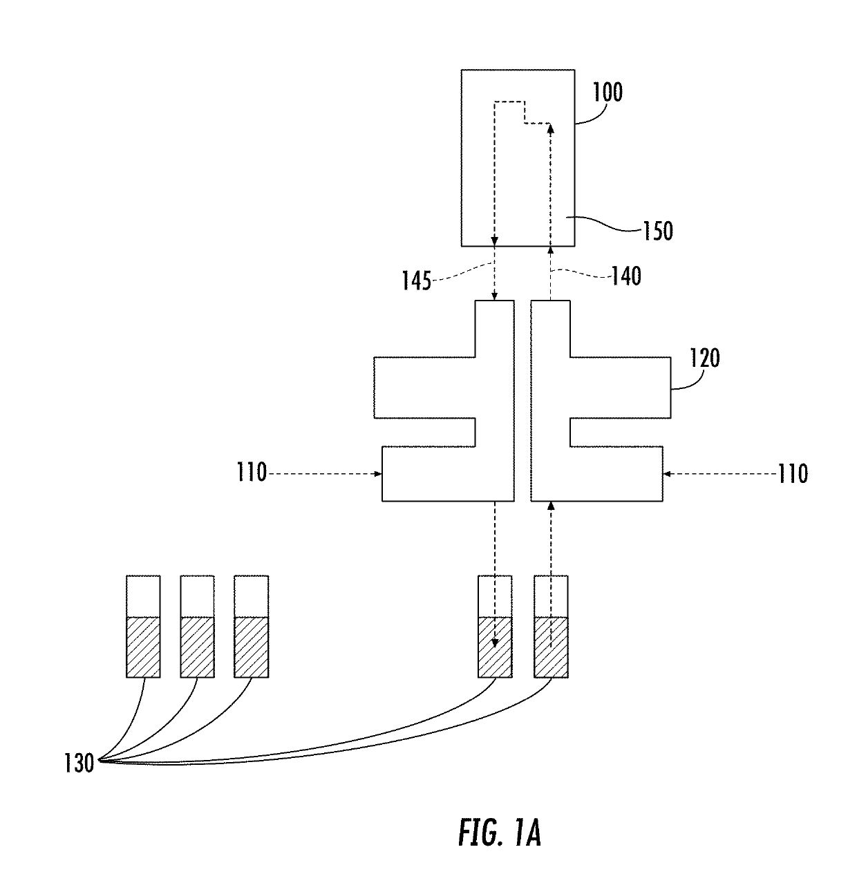
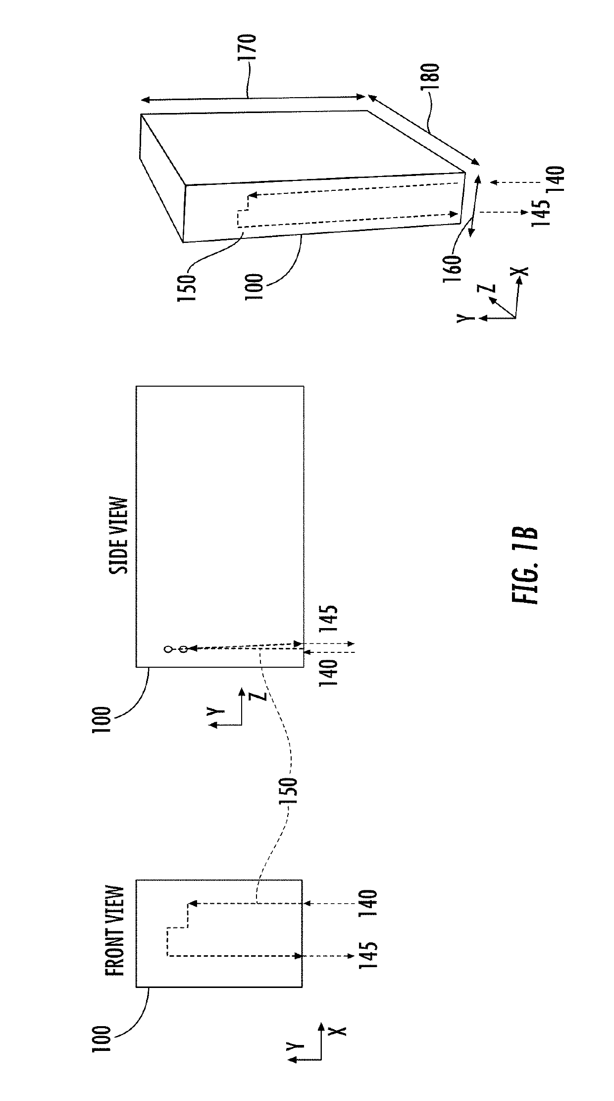
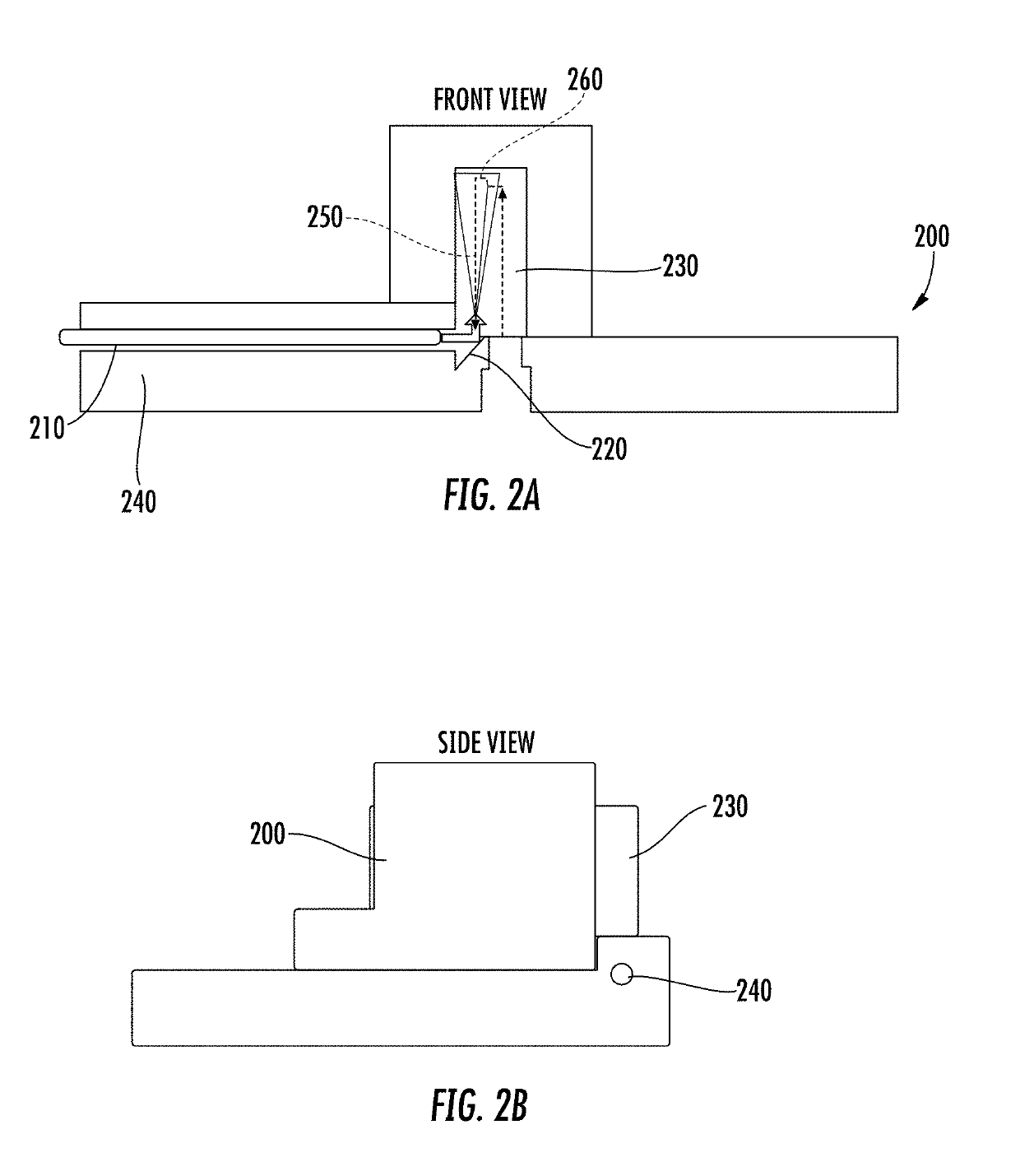
The present invention is a microfluidic chip that minimizes particle settling and improves imaging and analysis. The chip has a unique design with a long channel that allows for fluid injection and analysis at the highest point of the chip. The chip also has a second imaging device that can aid in visual alignment and increase accuracy and range of measurements. The invention also includes a manifold that allows for vials to be connected to the chip and the contents of the vials to be injected from the bottom of the chip. Overall, the invention improves the accuracy and range of measurements and analysis, and allows for multiple images to be analyzed and processed.

Problems solved by technology

The connection to the chip is horizontal, which, combined with the dead volume (empty space in fluidic connections that is to some extent unavoidable) in the connection, led to significant additional settling due to gravity.
Such a configuration also necessitates a relatively large diameter channel required by the connection, which, in addition to the dead volume, creates an area of relatively low velocity, further increasing the problem of particle settling.
This is not intuitive and required much experimentation to realize the problem before designing the current embodied solution.
Moreover, due to constraints in the prior art, multiple horizontal runs are required, causing cells to settle in multiple places in the channels.
This, in turn, causes a decrease in image quality because of the need to image through additional material at the edge of the chip.

Method used


Image

  • Microfluidic chip device for optical force measurements and cell imaging using microfluidic chip configuration and dynamics
  • Microfluidic chip device for optical force measurements and cell imaging using microfluidic chip configuration and dynamics
  • Microfluidic chip device for optical force measurements and cell imaging using microfluidic chip configuration and dynamics

Examples


example 1

Assessment of T-Cell Activation

[0080]Frozen Human Peripheral Blood Pan-T cells were obtained from a commercial source. The cells were thawed into medium and seeded into 96 well plates at a concentration of 1e6 cells / mL. Treated cells received 5 μL of IMMUNOCULT™ (STEMCELL™ Technologies, Vancouver Canada) activator per well (200 μL), while untreated cells received only medium (mock). Cells were treated on Day 0 and both treated and untreated cells were harvested every 24 hours for 4 days starting on Day 1. Harvested cell samples were centrifuged and the pellet was resuspended in LUMACYTE™ (Charlottesville, Va.) stabilization fluid at a concentration of approximately 5e5 cells / mL prior to analysis with a RADIANCE™ instrument. A portion of each cell sample was also fixed and labeled with a CD25 antibody and measured using a flow cytometer in order to confirm activation. Changes were seen in multiple parameters as a result of treatment demonstrating the potential to monitor T cell activ...


PUM

PropertyMeasurementUnit
diameteraaaaaaaaaa
diameteraaaaaaaaaa
lengthaaaaaaaaaa

Abstract

Provided are methods and devices for assessing biological particles for use in cell immunotherapy. By utilizing a microfluidic chip device together with optical force measurement and cell imaging, the methods enable comprehensive assessment and characterization of biological particles with regard to morphology, motility, binding affinities, and susceptibility to external forces, including but not limited to, chemical, biochemical, biological, physical and temperature influences. The methods enable the selection and production of biological particles, such as engineered T-cells, for use in immunotherapy and biomanufacturing.

Description

CROSS REFERENCE TO RELATED APPLICATIONS[0001]This application is a continuation-in-part application of U.S. patent application Ser. No. 15 / 853,763 filed Dec. 23, 2017 and is related to PCT / US17 / 68373 filed Dec. 23, 2017; both applications are incorporated by reference herein in their entirety.BACKGROUNDField of the Invention[0002]This invention relates in general to a device and method for particle analysis and imaging for particles or cells in fluids, and in particular to a device and method for particle imaging for fluids using pressure, fluid dynamics, electrokinetic, and optical forces. The invention further relates to particle analysis for purposes of cell therapy. The device and methods provided herein comprise the use and application of laser force cytology microfluidic designs for analyzing and sorting cells in cell therapy (i.e. immunotherapy) applications.[0003]The present invention is directed to a microfluidic chip wherein injection occurs in an upwards vertical directio...

Claims


Application Information

Patent Timeline
Patent Type & Authority Applications(United States)
IPC IPC(8): G01N15/14B01L3/00
CPCB01L3/502761G01N2015/1006B01L2200/0652G01N15/1484G01N15/1434G01N2015/1445G01N2015/1493G01N15/147G01N15/0227G01N21/6458G01N15/1433G01N15/149G01N15/00A61F2002/30677
Inventor HART, SEANHEBERT, COLIN
Owner LUMACYTE INC
Learn More