Method for making organic light emitting diode
a light-emitting diode and organic technology, applied in the field of organic light-emitting diodes, can solve the problems of affecting the uniformity of carbon nanotubes in the composite structure, and poor dispersion of carbon nanotubes in the melted polymer
- Summary
- Abstract
- Description
- Claims
- Application Information
AI Technical Summary
Benefits of technology
Problems solved by technology
Method used
Image
Examples
first embodiment
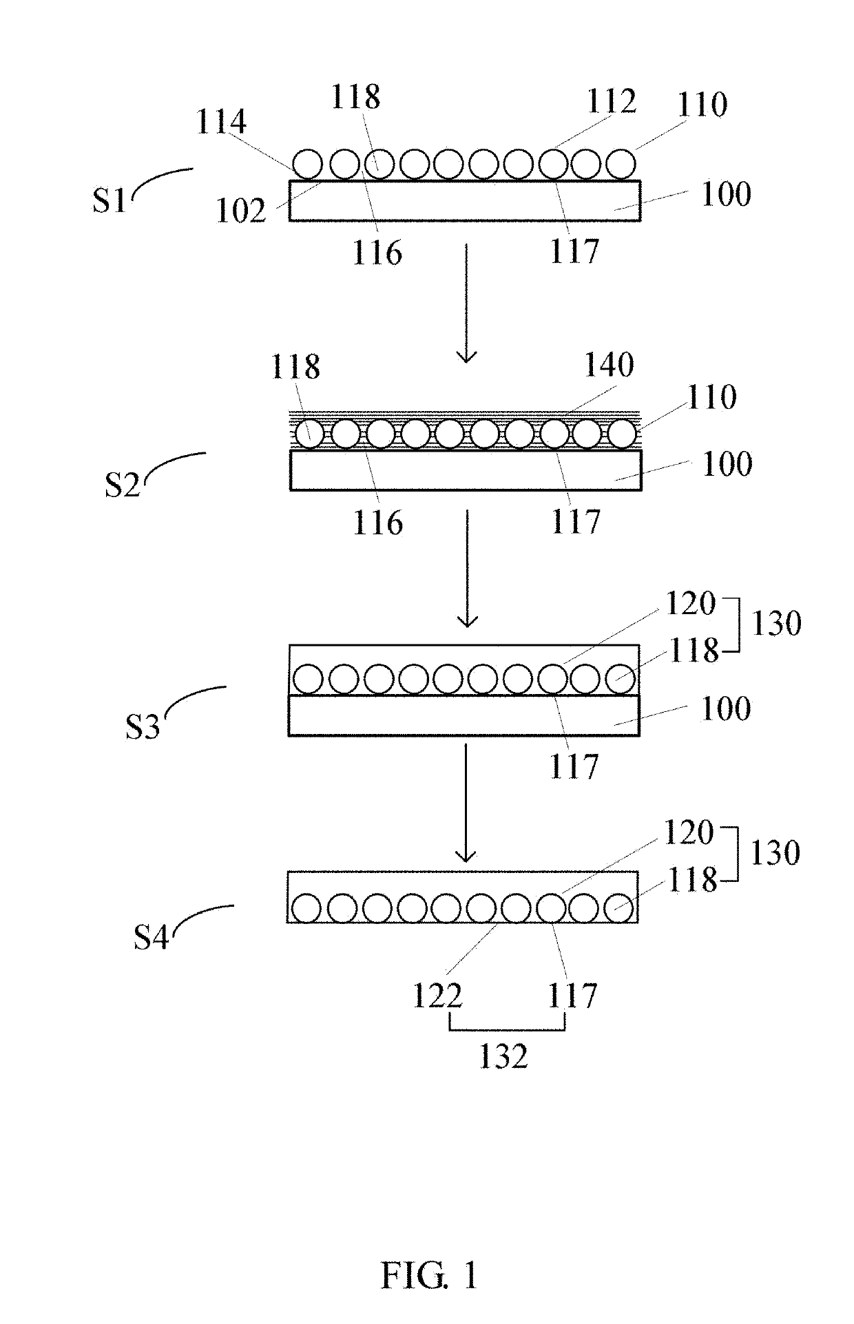
[0045]Referring to FIG. 1, a method for making a carbon nanotube composite structure 130 of a first embodiment includes the following steps:
[0046]S1, placing a carbon nanotube structure 110 on a substrate surface 102 of a substrate 100, wherein the carbon nanotube structure 110 has a first surface 112 and a second surface 114 opposite to the first surface 112, and the second surface 114 is in direct contact with the substrate surface 102;
[0047]S2, coating a monomer solution 140 on the carbon nanotube structure 110, wherein the monomer solution 140 is formed by dispersing a certain amount of monomers into an organic solvent;
[0048]S3, polymerizing the monomer; and
[0049]S4, removing the substrate 100.
[0050]In the step S1, the carbon nanotube structure 110 includes a plurality of carbon nanotubes 118 uniformly distributed therein. A gap 116 is defined between adjacent carbon nanotubes 118. The plurality of carbon nanotubes 118 is parallel to the first surface 112 and the second surface ...
second embodiment
[0069]Referring to FIG. 10, a method for making a carbon nanotube composite structure 160 of a second embodiment includes the following steps:
[0070]S21, placing the carbon nanotube structure 110 on the substrate surface 102 of the substrate 100, wherein the carbon nanotube structure 110 has the first surface 112 and the second surface 114 opposite to the first surface 112, and the second surface 114 is in direct contact with the substrate surface 102;
[0071]S22, locating a graphene layer 150 on the first surface 112;
[0072]S23, coating a monomer solution 140 on the graphene layer 150 and the carbon nanotube structure 110, wherein the monomer solution 140 is formed by dispersing the monomer into the organic solvent;
[0073]S24, polymerizing the monomer; and
[0074]S25, removing the substrate 100.
[0075]In this embodiment, the method for making the carbon nanotube composite structure 160 is similar to the method for making the carbon nanotube composite structure 130 above except that the gra...
third embodiment
[0077]Referring to FIG. 11, a method for making a carbon nanotube composite structure 170 of a third embodiment includes the following steps:
[0078]S31, placing the carbon nanotube structure 110 on the substrate surface 102 of the substrate 100 to form a preform structure 172, wherein the carbon nanotube structure 110 has the first surface 112 and the second surface 114 opposite to the first surface 112, and the second surface 114 is in direct contact with the substrate surface 102;
[0079]S32, locating two preform structures 172 on a base 174, wherein the two preform structures 172 are spaced apart from each other, the substrates 100 of the two preform structures 172 and the base 174 form a mold 176 having an opening, and the carbon nanotube structures 110 of the two preform structures 172 are opposite to each other and inside of the mold 176;
[0080]S33, injecting the monomer solution 140 into the inside of the mold 176 from the opening of the mold 176, wherein the monomer solution 140...
PUM
| Property | Measurement | Unit |
|---|---|---|
| angle | aaaaa | aaaaa |
| diameter | aaaaa | aaaaa |
| diameter | aaaaa | aaaaa |
Abstract
Description
Claims
Application Information
 - R&D
- Intellectual Property
- Life Sciences
- Materials
- Tech Scout
- Unparalleled Data Quality
- Higher Quality Content
- 60% Fewer Hallucinations
Browse by: Latest US Patents, China's latest patents, Technical Efficacy Thesaurus, Application Domain, Technology Topic, Popular Technical Reports.
© 2025 PatSnap. All rights reserved.Legal|Privacy policy|Modern Slavery Act Transparency Statement|Sitemap|About US| Contact US: help@patsnap.com


