
Hydrogen-Producing Device and Operation Method of Hydrogen-Producing Device

Inactive Publication Date: 2019-08-15
SAWAFUJI ELECTRIC COMPANY
View PDF0 Cites 4 Cited by
  • Summary
  • Abstract
  • Description
  • Claims
  • Application Information

AI Technical Summary

Benefits of technology

The present invention relates to a hydrogen-producing device that can start up autonomously and produce hydrogen without receiving an energy supply from the outside. It can use a fuel battery as the energy source for starting up and producing hydrogen, eliminating the need for a storage battery. The fuel battery provides more power than the device needs, so the hydrogen production can be sustained without the need for additional heating or cooling. The device can operate at room temperature, making it simpler and more efficient than other types of hydrogen producers. Overall, this invention provides a cheaper, smaller, and more reliable way to produce hydrogen.

Problems solved by technology

Hydrogen tends to be costlier to store and transport compared to other fuels.
However, in cases where the supply of energy from the outside was cut off or stopped, such as during a power outage or a natural disaster, it was difficult to start up the hydrogen-producing device until the external energy supply was restored.
However, storage batteries having enough capacity to start up a hydrogen-producing device are large and expensive, and therefore a factor driving up the size and cost of the hydrogen-producing device as a whole.
Further, when using a storage battery as an emergency energy storage means, repeated charging and discharging gradually depletes the capacity of the storage battery, leading to the risk that the required electric power could not be supplied after a certain time of use.

Method used


Image

  • Hydrogen-Producing Device and Operation Method of Hydrogen-Producing Device
  • Hydrogen-Producing Device and Operation Method of Hydrogen-Producing Device
  • Hydrogen-Producing Device and Operation Method of Hydrogen-Producing Device

Examples


examples

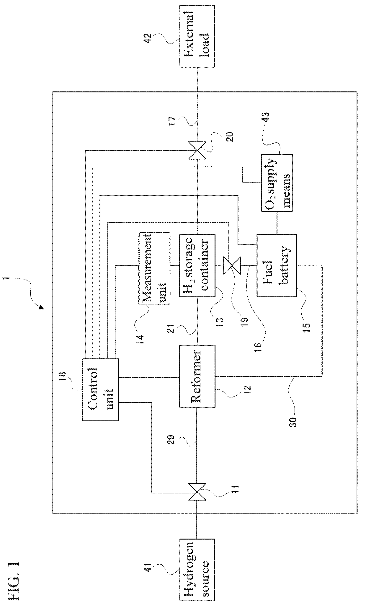
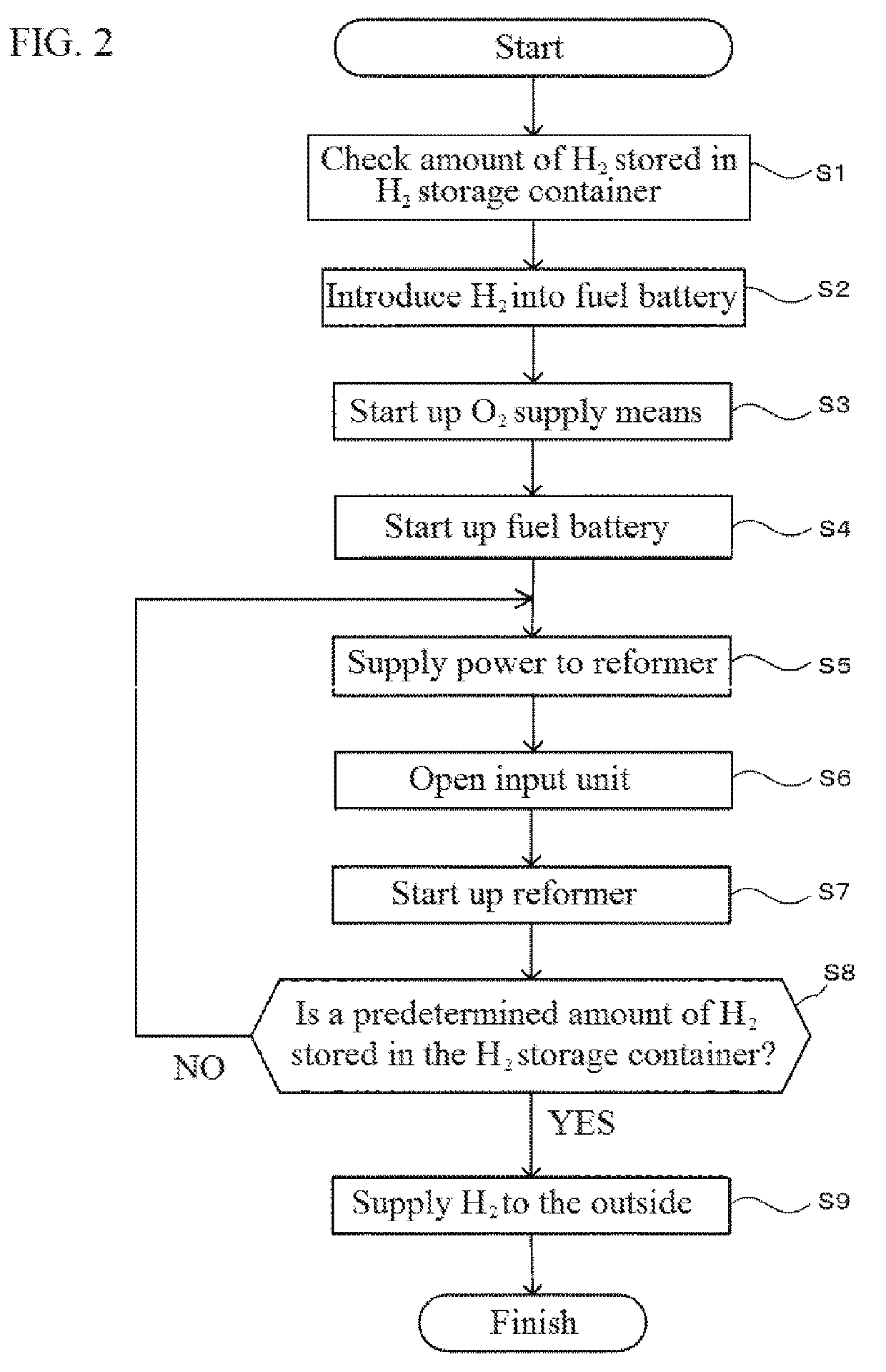
[0048]Below is shown an Example of autonomous start-up of the hydrogen-producing device 1 including the reformer 12 and the fuel battery 15. The present Example employs as the fuel battery 15 a solid polymer fuel battery having a start-up hydrogen amount of 50 liters (0.05 m3) at 0.1 MPa (1 standard atmosphere).

[0049]In the present Example, a pressure gauge is employed as the measurement unit 14 for measuring the storage amount of the hydrogen-containing gas in the hydrogen storage container 13. The control unit 18 stores a threshold value of pressure corresponding to the amount of hydrogen-containing gas necessary for start-up of the fuel battery 15. During hydrogen production, the control unit 18 monitors the measured results of the measurement unit 14, and performs feedback control of the amount of hydrogen-containing gas produced by the reformer 12 and the storage amount of the hydrogen storage container 13 using the results of a comparison of the stored threshold value with the...


PUM


Abstract

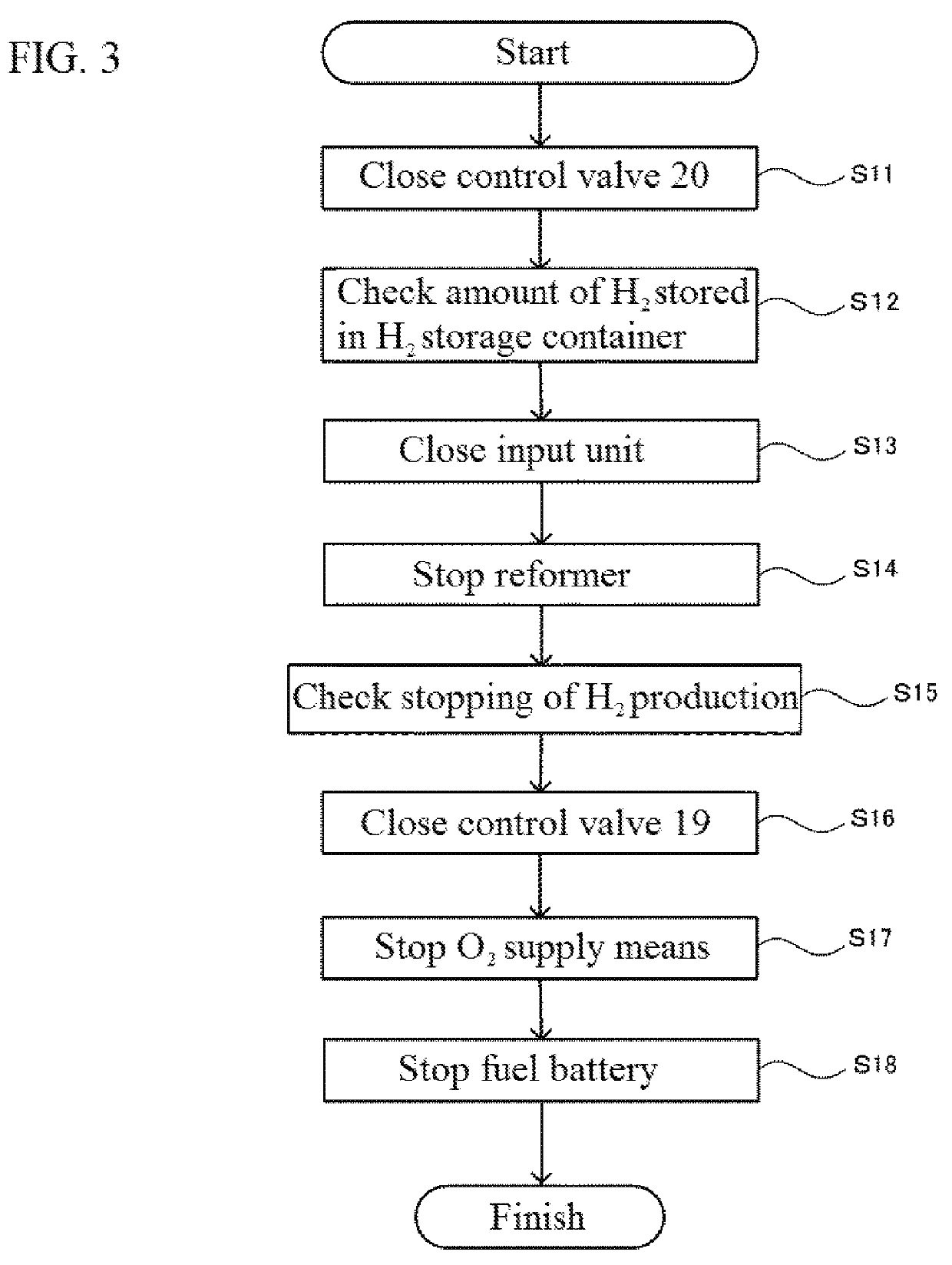
A hydrogen-producing device is provided which can start up without receiving an energy supply from the outside. This hydrogen-producing device 1 is provided with an input unit 11 which is connected to a hydrogen source 41, a reformer 12 which produces a hydrogen-containing gas, a hydrogen storage container 13, a fuel battery 15 which generates power using the hydrogen-containing gas, and a control unit 18. The hydrogen storage container 13 is connected to a fuel hydrogen supply path 16 for supplying hydrogen to the fuel battery 15, and to an external supply path 17 which supplies hydrogen to an external load 42. The control unit 18 stores a threshold value of the hydrogen-containing gas necessary for start-up of the fuel battery 15, and controls the amount stored in the hydrogen storage container 13 to be greater than or equal to the amount necessary for start-up of the fuel battery 15. Further, when starting up the hydrogen-producing device, the fuel battery 15 generates power by receiving a supply of the hydrogen-containing gas stored in the hydrogen storage container 13 and supplies power to the reformer 12 from a power supply path 30. The reformer 12 starts up and hydrogen is produced.

Description

FIELD OF THE INVENTION[0001]The present invention relates to hydrogen-producing devices. In particular, the invention relates to a hydrogen-producing device which is capable of starting up and continuing hydrogen production without receiving an energy supply from the outside.DESCRIPTION OF THE RELATED ART[0002]Hydrogen tends to be costlier to store and transport compared to other fuels. Because of this, there is an intrinsic demand for on-site production of hydrogen, by installing a hydrogen-producing device adjacent to a device that uses hydrogen, or incorporating a hydrogen-producing device in equipment that uses hydrogen.[0003]A known hydrogen production method consists of decomposing a hydrogen source such as ammonia, urea, or a hydrocarbon gas to produce hydrogen. A device used for decomposing a hydrogen source is usually called a reformer. A reformer needs to be supplied with energy from the outside on start-up, and a hydrogen-producing device is thus normally connected to, fo...

Claims


Application Information

Patent Timeline
IPC IPC(8): H01M8/04225H01M8/0606H01M8/0612H01M8/04313H01M8/04746H01M8/04858H01M8/04302B01J19/08C01B3/04C01B3/22C01B3/50
CPCH01M8/04225H01M8/0606H01M8/0618H01M8/04313H01M8/04776H01M8/04932H01M8/04302B01J19/08C01B3/047C01B3/22C01B3/501H01M2250/10H01M2008/1095C01B2203/0272C01B2203/041B01J2219/0894B01J2219/0869B01J7/00B01J19/088B01J2219/0801B01J19/2475B01J2219/0805B01J2219/0809B01J2219/0824C01B2203/0861C01B2203/0405C01B2203/1647C01B2203/1685C01B2203/066H01M8/0625H01M8/222Y02E60/36Y02E60/50Y02B90/10H01M8/0612H01M8/04746C01B3/04H01M8/04858H01M8/10H01M8/04
Inventor MIURA, TOMONORI
Owner SAWAFUJI ELECTRIC COMPANY
Learn More