
Permselective membrane type reactor and method for hydrogen production

a membrane type reactor and selective membrane technology, applied in the direction of oxygen/ozone/oxide/hydroxide, chemical/physical/physical-chemical process catalysts, physical/chemical process catalysts, etc., can solve the problem of not being able to feed the generated heat to the whole portion of the catalyst layer, incurring a reduction in heat efficiency, and the temperature of the reactor exceeding the allowable limit. , to achieve the effect of suppressing undesirable local heat generation, feeding efficient heat, and promoting

Inactive Publication Date: 2008-09-18
NGK INSULATORS LTD
View PDF8 Cites 32 Cited by
  • Summary
  • Abstract
  • Description
  • Claims
  • Application Information

AI Technical Summary

Benefits of technology

[0010]The task of the present invention is to provide a permselective membrane type reactor having a hydrogen permselective membrane, wherein an auto thermal type reforming reaction is conducted to efficiently feed the heat required for the reaction and produce hydrogen, and a method for producing hydrogen.
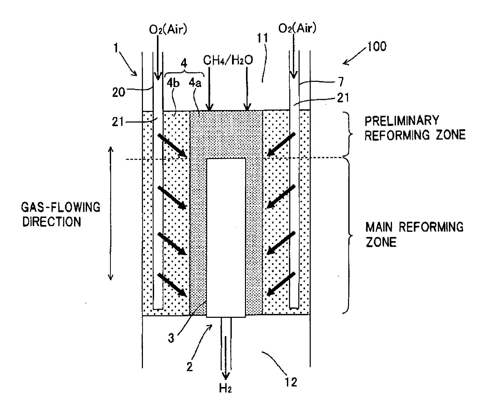
[0015]In a permselective membrane type reactor, by providing an oxygen-containing gas feeding section to feed an oxygen-containing gas to the catalyst layer from multiple-positions in the gas-flowing direction, it is possible to balance the heat absorbed in the reforming reaction and the heat generated in the combustion reaction and feed a heat efficiently to promote a reaction. That is, by feeding air (oxygen) from multiple-positions to control the amount of heat to be generated, it is possible to suppress undesirable local heat generation, feed a heat efficiently, and produce hydrogen satisfactorily. Further, since the local high-temperature generation inside the permselective membrane type reactor can be prevented, the durability of permselective membrane can be increased. In the present reactor, since the heat required for reforming reaction can be fed from inside the reactor, high heat efficiency can be attained. Moreover, since the heating from outside is unnecessary, the reactor can be made compact.

Problems solved by technology

Therefore, in the auto thermal type reforming reaction, if air (oxygen) is fed at one time, a combustion reaction may proceed locally, which makes it impossible to feed the generated heat to the whole portion of catalyst layer and incurs a reduced heat efficiency.
Further, when a sudden combustion reaction takes place, the reaction heat may cause the temperature of a reactor exceed its allowable limit, which is dangerous.
Furthermore, when a sudden combustion reaction takes place in the vicinity of a permselective membrane, the membrane is exposed to a high temperature, which may affect the durability of the membrane.

Method used


Image

  • Permselective membrane type reactor and method for hydrogen production
  • Permselective membrane type reactor and method for hydrogen production
  • Permselective membrane type reactor and method for hydrogen production

Examples


embodiment 1

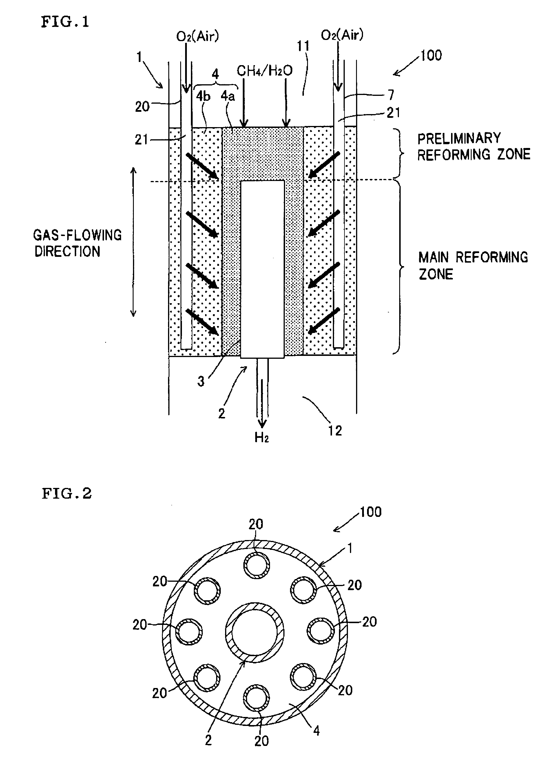
[0025]FIG. 1 and FIG. 2 schematically show an embodiment of the permselective membrane type reactor of the present invention. FIG. 1 is a sectional view cut along a plane including the central axis, and FIG. 2 is a plan view of the reactor. As shown in FIG. 1 and FIG. 2, the permselective membrane type reactor 100 of this embodiment comprises:

[0026]a cylindrical reaction tube 1 having a gas inlet 11 at one end and a gas outlet 12 at the other end,

[0027]a cylindrical, bottomed, separation tube 2 inserted into the reaction tube 1, which is made of a porous substrate material and has a permselective membrane 3 on the surface, and

[0028]a catalyst layer 4 provided between the reaction tube 1 and the separation tube 2, for promotion of chemical reaction.

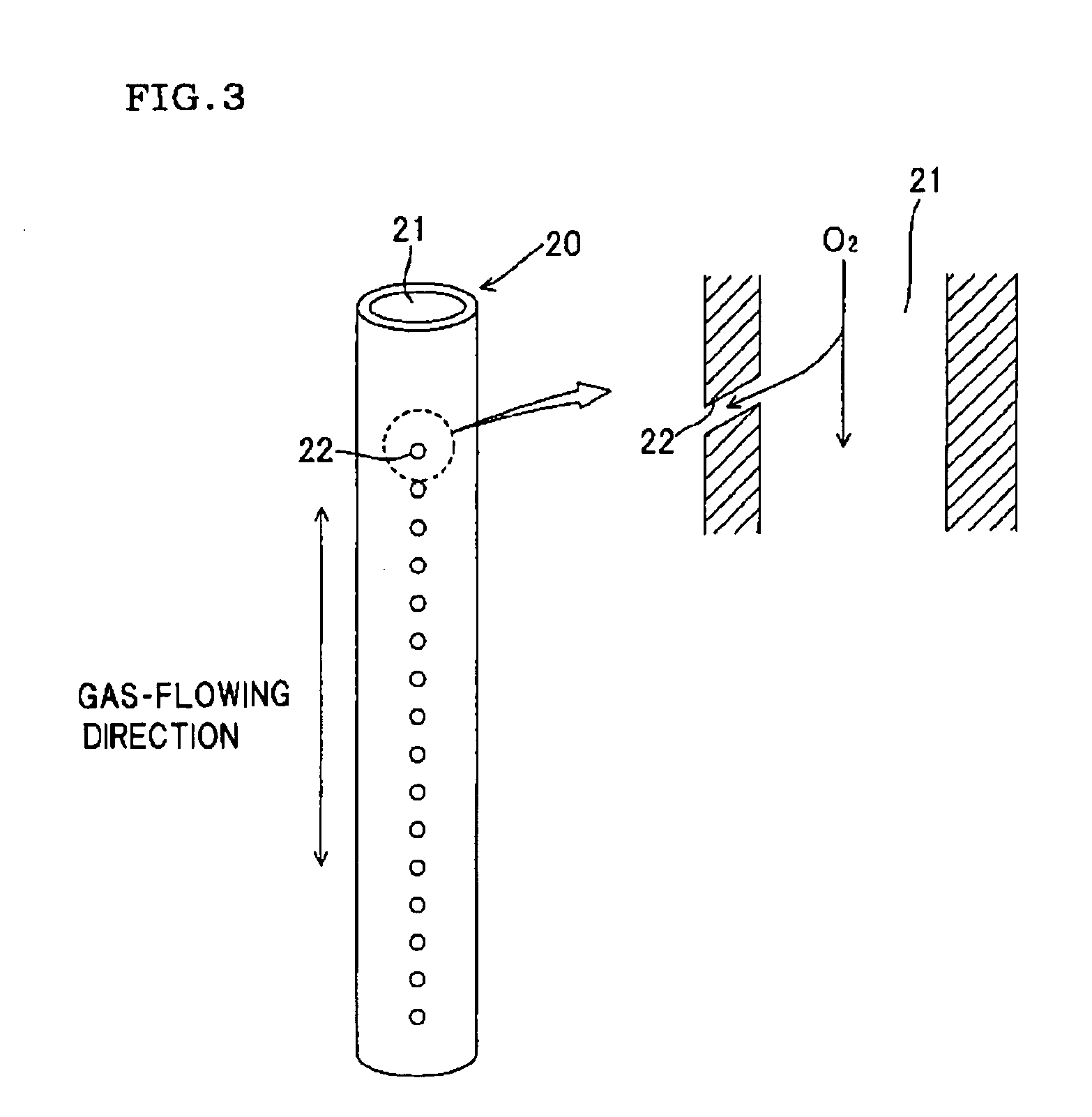
[0029]The reactor 100 further comprises, at a location apart from the permselective membrane 3, an oxygen-containing gas feeding section 20 which extends in the gas-flowing direction of the reaction tube 1 and feeds an oxygen-containing ga...

embodiment 2

[0042]Embodiment 2 of the present invention is described with reference to FIG. 4 and FIG. 5. An oxygen-containing gas-feeding section 20 is outside a separation tube 2; the separation tube 2 is disposed in the central portion of the oxygen-containing gas feeding section 20; and a space formed by the outer wall 25 and inner wall 26 of the oxygen-containing gas feeding section 20 is an oxygen-containing gas passage 21. The two walls are made of a porous material and function as ports for discharging an oxygen-containing gas. That is, the oxygen-containing gas feeding section 20 of the present embodiment is made of a porous material and, therefore, the walls function as ports and the oxygen-containing gas is discharged therefrom. There is no particular restriction as to the porous material as long as it is a ceramic material, however for example, alumina, mullite, cordierite, silicon carbide and silicon nitride are preferably used. The ceramic porous material has a role of a tube disc...

example 1

[0048]A cordierite-made porous material was disposed in a reactor as shown in FIG. 4 and air was fed therethrough to a catalyst layer at O2 / C=0.5. The cordierite-made porous material had an average pore diameter of 0.1 μm. As a catalyst, a physical mixture (a simple mixture) of pellet-like rhodium alumina and ruthenium alumina was used. The ratio of air fed to the pre-reforming zone to air fed to the main reforming zone was 40:60.


PUM

PropertyMeasurementUnit
Fractionaaaaaaaaaa
Permselectivityaaaaaaaaaa

Abstract

A permselective membrane type reactor 100 comprises:a cylindrical reaction tube 1 having a gas inlet 11 at one end and a gas outlet 12 at the other end,a cylindrical, bottomed, separation tube 2 inserted into the reaction tube 1, which is made of a porous material and has a permselective membrane 3 at the surface, anda catalyst layer 4 provided between the reaction tube 1 and the separation tube 2, for promotion of chemical reaction. The reactor 100 further comprises, at a location apart from the permselective membrane 3, an oxygen-containing gas feeding section 20 which extends in the gas-flowing direction of the reaction tube 1 and feeds an oxygen-containing gas from multiple positions to the catalyst layer 4 in the gas-flowing direction.

Description

BACKGROUND OF THE INVENTION AND RELATED ART STATEMENT[0001]The present invention relates to a permselective membrane type reactor used for forming hydrogen from a main raw material gas which is a hydrocarbon such as methane, butane, or kerosene; an alcohol such as methanol or ethanol; ether such as dimethyl ether; or ketone by a reforming reaction or the like, and then separating and taking out the hydrogen, as well as to a process for producing hydrogen using the reactor.[0002]Hydrogen is being used in a large amount as a basic raw material gas in the petrochemical industry. Especially, in recent years, hydrogen has drawn attention as a clean energy source in fields such as fuel cell. Thus, use of hydrogen in wider fields is expected. The hydrogen used for such purposes is formed from a main raw material gas which is a hydrocarbon such as methane, butane, or kerosene; an alcohol such as methanol or ethanol; ether such as dimethyl ether; or ketone by a reforming reaction, a partial ...

Claims


Application Information

Patent Timeline
IPC IPC(8): C01B3/26B01J19/00
CPCB01J8/0411C01B2203/1241B01J8/0496B01J19/2475C01B3/384C01B3/501C01B13/0251C01B2203/0233C01B2203/0283C01B2203/041C01B2203/0475C01B2203/0495C01B2203/0811C01B2203/1047C01B2203/1058B01J8/0492
Inventor NAKAMURA, TOSHIYUKIMORI, NOBUHIKOYOSHIDA, MANABU
Owner NGK INSULATORS LTD
Learn More