Active electrical transmission system

a transmission system and electrical technology, applied in the direction of motors, single network parallel feeding arrangements, ac network load balancing, etc., can solve the problem of notoriously unreliable wind power, achieve the effect of reducing fuel costs, reducing stress on supporting insulators, and improving the return on investment in wind power

Inactive Publication Date: 2005-06-09
GOULD LEN CHARLES
View PDF0 Cites 29 Cited by
  • Summary
  • Abstract
  • Description
  • Claims
  • Application Information

AI Technical Summary

Benefits of technology

[0008] It is an object of the present invention to gain economic advantage by substituting the towers of new high voltage transmission lines with the tall and sturdy towers typically used to support large wind turbines. The somewhat sub-optimal siting of the turbines e.g. being required to follow the route of the transmission corridor, can be justified economically by the reductions in capital cost of installation achieved by sharing the towers with the transmission line, and also slightly by making taller towers economically justifiable which improves the performance of a wind turbine.
[0009] A further object of the present invention is to gain economic advantage by installing at some or all of the wind generators mounted on the transmission line towers an auxiliary electrical generating system to supplement the wind turbine power output during periods of peak demand of the customers serviced by the transmission line. It is unfortunate that wind power is a notoriously unreliable power source, typically providing on average less than 33% of the rated output of the generator. Installing a heat engine onto the gearbox of the wind turbine would add only a small percentage of weight and cost to the installation while enabling the turbine to then guarantee full rated output during peak demand periods. As an alternative, if the supplemental power wire provided by typical fuel cells then the added weight can be removed from the top of the tower and no special connections to the wind turbine gearbox would be required.
[0011] In a first preferred embodiment of the present invention, 8 aluminum tubes 140 mm diameter (nominal 5″) and having 2.5 mm thick walls and supported by 8 steel cables each having a 125 square millimeter cross section, all suspended on towers spaced at 450 meter intervals with a 9% sag can transmit 2.8 gigawatts electrical for 1000 kilometers with only 3.68% electrical losses at 1000 KV DC. The 1000 KV DC is transmitted as 500 KV+ on one side of the tower and 500 KV− on the other side, thus reducing the stress on the supporting insulators to the same as would be seen on a 345 KV AC line. These same pipes operating at 68 bar (1000 psi) can also transmit 1133 megawatts of Natural Gas fuel at 1.33% compression losses per 160 km. Further, having 75% of the towers each carry a 1.5 megawatt wind turbine supplemented by an auxiliary 1.5 megawatt gas turbine engine, an additional 2.5 gigawatts of dispatchable peak power and (at 30% wind reliability) an additional 0.55 gigawatts of off-peak wind generated power is available to sell at the end of the line. The incremental capital cost of the fuel supplemented wind generation is approximately one to one point five million dollars per megawatt above the cost of a standard electrical transmission line. The power generated by the wind turbines is transmitted between towers at nominal 30 Kv AC generator voltage, or as comparable voltage DC, on an underhung set of secondary conductors until sufficient capacity is available to justify a step-up connection to the main transmission conductors. Benefits include a) reduced fuel cost because a part of the added power (8% of peak power, 100% offpeak) is wind generated, b) improved return on capital invested in wind generators due to improved capacity factor, c) significant reduction of electrical transmission losses due to increased aluminum conductor cross section. For a small additional cost as according to the US National Renewable Energy Laboratory document from contract No. DE-AC36-99-G010337 cited above, the towers of the turbines can be modified to act as fuel gas storage tanks at moderate pressure, enabling the fuel to be purchased and stored at optimum prices at several points along the line and transported to the generators for only the incremental cost of compression above the delivery pressure. Each tower can store approximately enough fuel to supply a 1.5 megawatt gas turbine 40 hrs per week for several weeks depending on tower wall thickness. A transmission line constructed in this manner is an ideal means of transporting electrical power from a mine-mouth or underground gasifier coal fired generating station in the midwest to the heavy load centres of the midwest or the west coast, since the distances are large, fuel gas is readily available at the coal beds or along the route, and wind conditions along the route are often ideal for wind turbines.
[0012] In a second embodiment of the present invention, all is constructed according to the first embodiment described above except the supplemental gas turbine engine connected to the wind generator is replaced by bidirectional hydrogen fuel cells such as the Proton Exchange Membrane cells manufactured by ProtonEnergy Inc. The weight of these fuel cells in current technology means they must be installed at ground level, and switching from natural gas to hydrogen reduces the capacity of the pipes on a megawatt thermal per hour basis to 79% of that stated above, but there would also be benefits. First, as electrolyzers the units are capable of producing the hydrogen fuel required for peaking at or near pipeline pressure, significantly reducing compressor costs and losses. Second, the fuel cells are capable of producing more hydrogen than would be required for peaking generation and the transmission lines are capable of delivering this excess economically to market points along the transmission line, thus providing a secondary market for offpeak electricity produced by the power station at the end of the line.
[0014] In all embodiments of the present invention, the designer may choose to lay out the path of the vertical supporting towers in a catenary curve between tension towers e.g. approximately every ten towers, with the bow of the curve facing away from the prevailing wind direction. This allows the tension on the conductors to assist the towers in resisting the added horizontal loading of wind forces on the conductors from all wind directions except opposite to the prevailing direction, thus enabling the engineer to safely reduce the amount of additional support required over a standard wind turbine tower, provided the controls of the wind turbine reduce or stop wind power generation if the wind direction changes to opposite the prevailing direction. Typical wind rose maps indicate that in most locations this strategy will only reduce net wind generated power by a very small percentage. Calculations indicate that for a DC transmission line with 2 sets of four nominal 125 mm (5 inch) tubes strung in a horizontal pattern, the horizontal wind loading of the tubes on the tower in a 45 meter per second wind (100 mph) would be approximately double the loading of a 1.5 megawatt wind turbine at full power. Whether the engineer chooses to construct the towers to handle all possible loads directly, and incidentally increase the fuel storage pressure capability of the towers, or use conductor tension to mitigate part of the loads would depend on the circumstances of particular installations or even particular spans of towers.

Problems solved by technology

It is unfortunate that wind power is a notoriously unreliable power source, typically providing on average less than 33% of the rated output of the generator.

Method used


Image

  • Active electrical transmission system
  • Active electrical transmission system
  • Active electrical transmission system

Examples


third embodiment

[0047]FIG. 12 is a detail of the base of a transmission and generator tower constructed according to the invention showing a bi-directional fuel cell / electrolyser auxiliary power unit 60 connected electrically to the secondary conductors 10 by cable 61. The bidirectional fuel cell / electrolyser units may be Proton Exchange Membrane fuel cell / electrolysers as are manufactured by ProtonEnergy Corporation, USA, or SOFC fuel cell / electrolysers as are manufactured by several companies particularly those who were suppliers of the INEEL evaluations of this process, or any other suitable means. In this embodiment of the invention the secondary conductors are operated as DC at the rated input voltage of the fuel cell / electrolyser and generator unit, while the wind turbine, having either no auxiliary engine installed or a Rankine engine suited to waste heat recovery from SOFC electrical generation or possibly even any heat engine as in the descriptions above of FIGS. 10 or 11, simply rectifies...

first embodiment

[0049]FIG. 14 is a layout of a line of transmission and generator towers 71 installed in a horizontal catenary curve 72 or an arc 73 of radius equal the distance between the two supporting strain towers 70. The circles indicating the strain towers at 70 are exaggerated in scale by a factor of 11. This layout takes advantage of the fact that in most locations, as can be determined on typical wind rose maps, a design basis wind force will almost always blow from a prevailing direction, in this case indicated by wind direction arrow 74, while rarely if ever blowing from an opposite direction plus or minus 22.5 degrees, as indicated by wind direction arrows 75 and 76. By using a curved transmission line layout as indicated, the tension of the suspended conductors is easily transferred to heavy cable guys at the strain poles. But these guys and the conductor tension also provide a preload strain on the wind tower poles equal in the example illustrated to cos(5.7)*total conductor tension ...

fourth embodiment

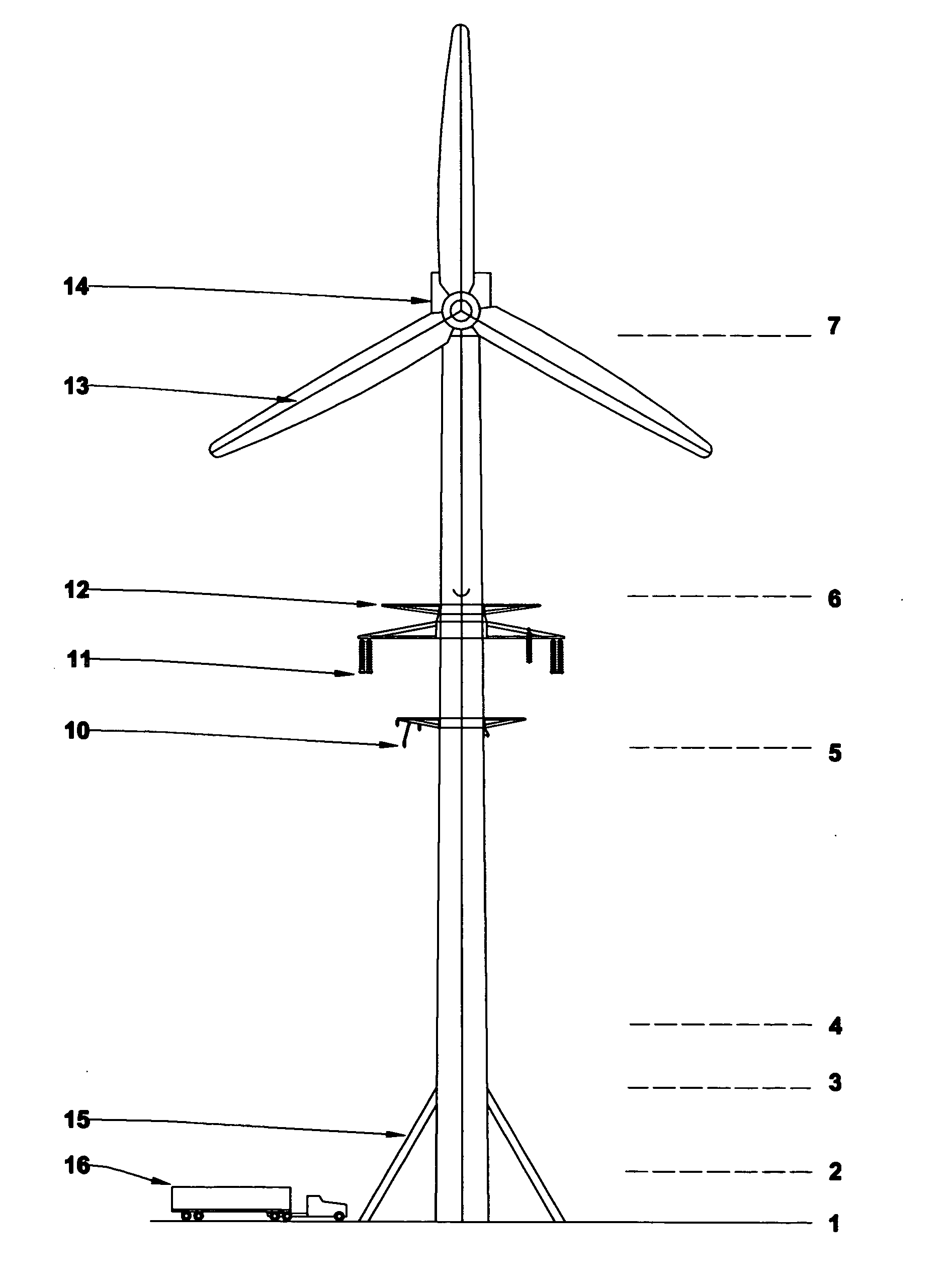
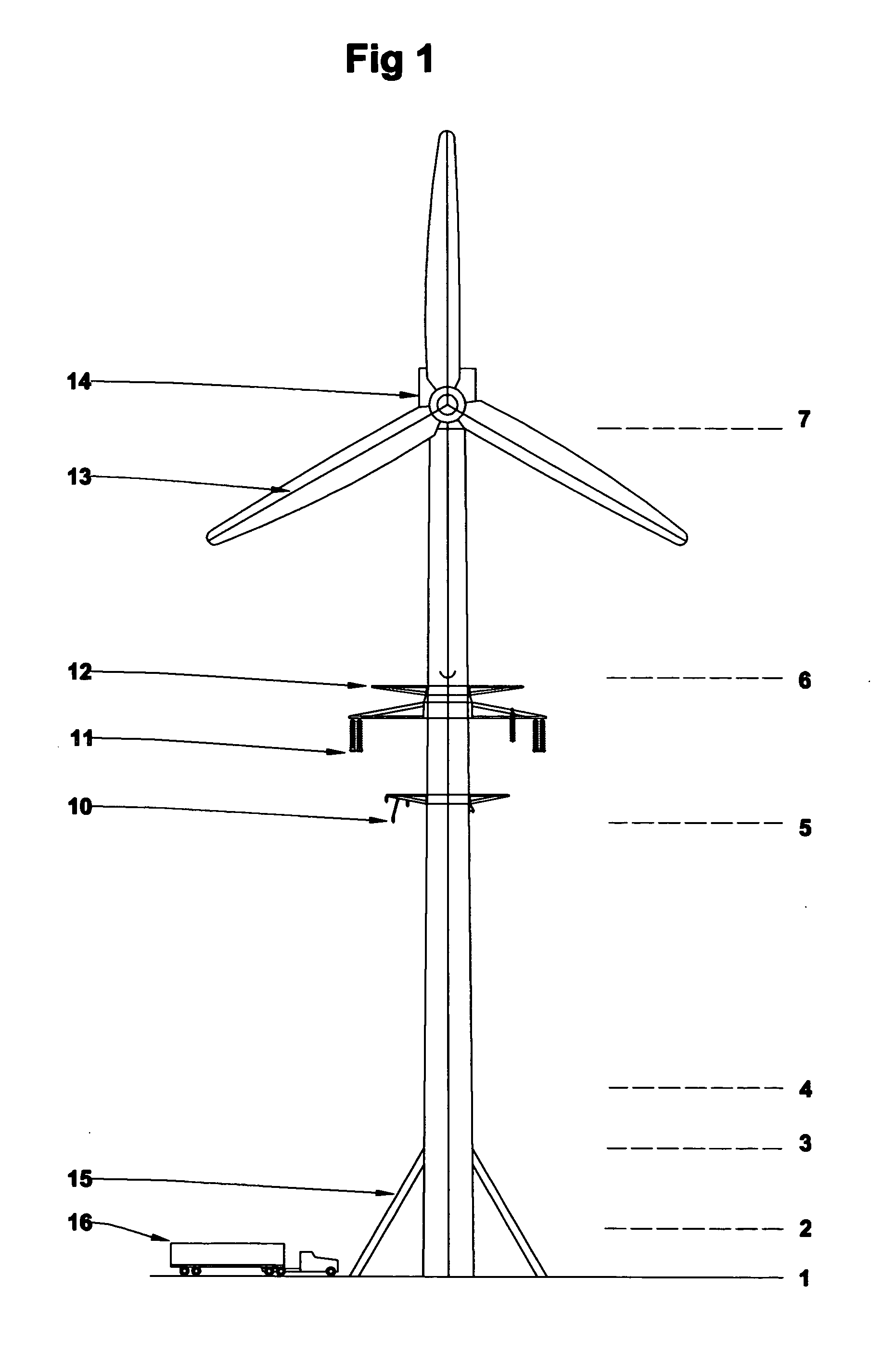
[0050]FIG. 15 is an end view of a transmission and generator tower constructed according to the present invention showing three phase alternating current primary conductor tubes and underhung secondary conductors. All distances and indicated items are the same as in FIG. 1 but for the addition of Level line 4a which indicates the added height of this tower over a standard 82 meter tall tower of 36.5 meters, line 6a which indicates the new lowest point of the turbine blades 13 during their rotation, and line 8 which indicates the total height of the tower at 116.5 meters.

[0051]FIG. 16 is a detail cross section of the conductors of a transmisssion line formed of conductive walled tubes having installed in their interior 70 or on their exterior 71 an electrically isolated conductor of small cross section and relatively higher resistance than the main conductor tubes. At all times this conductor is electrically connected to the primary conductors at the transmitting end of the transmiss...


PUM


Abstract

An electrical transmission line is provided which employs the conductive and structural material usually formed into current carrying cables to form the tubes of a pressurized pipeline which is then suspended from insulators on tall poles to create a low impedance electrical conductor and a high volume gas pipeline. The poles of wind generator towers may be employed to support the conductors and to store the gas from the pipeline. Auxiliary electrical generation may be added at the towers to assist in voltage or VAR support at times of peak load. Electrolysers may also be employed to increase electrical power consumption during offpeak times and supply the fuel gas or compressed air generated into the pipeline for sale or into storage for later re-conversion back into electricity at times of peak demand. A novel line layout plan is provided which reduces the cost of the transmission line.

Description

BACKGROUND OF THE INVENTION [0001] This invention applies to high voltage electrical power transmission systems. [0002] It is known to employ tubular conductors to transfer electrical power. Micheal W. Dew in U.S. Pat. No. 4,947,007 teaches the construction of an overhead superconducting transmission line in which the conductors are also tubes within a sheath tube, again for the purpose of supplying over very short sections of the line the cryogenic liquid required to maintain the conductors cold enough to acquire their superconductivity. No other purpose of the tubes is contemplated. [0003] Filmore O. Frye, in U.S. Pat. No. 5,565,652 teaches the construction of an electrical transmission line from conductive pipes laid within insulating plastic pipes. However no use is contemplated of the resulting pipeline to tranport any physical material and, in fact, this would be impossible in a line constructed according to his specification since in long straight runs the couplings are not t...

Claims


Application Information

Patent Timeline
Patent Type & Authority Applications(United States)
IPC IPC(8): F03D9/00H02G7/00H02G7/20H02J3/28H02J3/38H02J15/00
CPCF03D9/00H02G7/20H02J3/28H02J3/38H02J15/006Y02E70/10Y02E10/763Y02E10/766Y02E60/15Y02E70/30Y02E10/72Y02E10/728Y02E10/76Y02E60/36F03D9/25F03D13/20Y02E60/16
Inventor GOULD, LEN CHARLES
Owner GOULD LEN CHARLES
Why Eureka
Try Eureka