Low-pressure plasma chamber, low-pressure plasma installation and method for producing a low-pressure plasma chamber

a low-pressure plasma chamber and low-pressure plasma technology, which is applied in the direction of glass pressing apparatus, glass making apparatus, manufacturing tools, etc., can solve the problems of unnecessary complex electrode control or complex calculation and construction of electrodes

Active Publication Date: 2019-08-22
DIENER CHRISTOF HERBERT
View PDF1 Cites 0 Cited by
  • Summary
  • Abstract
  • Description
  • Claims
  • Application Information

AI Technical Summary

Benefits of technology

[0007]An object of the present invention is accordingly to provide in a structurally simple manner a low-pressure plasma chamber which enables a homogeneous plasma inside the low-pressure plasma c

Problems solved by technology

A complex calculation and construction of the electrode

Method used


Image

  • Low-pressure plasma chamber, low-pressure plasma installation and method for producing a low-pressure plasma chamber
  • Low-pressure plasma chamber, low-pressure plasma installation and method for producing a low-pressure plasma chamber
  • Low-pressure plasma chamber, low-pressure plasma installation and method for producing a low-pressure plasma chamber

Examples


Embodiment Construction

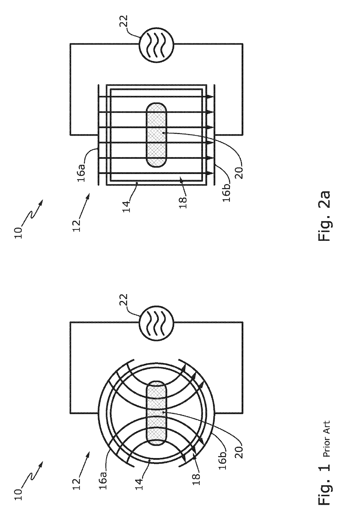
[0037]FIG. 1a shows a low-pressure plasma installation 10 according to the prior art. The term “prior art” is intended to be understood to mean that low-pressure plasma installations of the type according to FIG. 1a are known to the Applicant. However, this is not necessarily published prior art.

[0038]The low-pressure plasma installation 10 has a low-pressure plasma chamber 12 with a low-pressure plasma chamber body of glass. The low-pressure plasma chamber body 14 has a round, in this instance circular, cross-section. Electrodes 16a, 16b surround the low-pressure plasma chamber body 14 in a curved manner so that field lines 18 are present in a curved manner in the low-pressure plasma chamber 12. A component 20 for plasma processing is introduced in the low-pressure plasma chamber 12. The plasma is produced by means of a plasma voltage supply 22.

[0039]As a result of the curved field lines 18, the plasma ignited in the low-pressure plasma chamber body 14 is inhomogeneous. An object o...


PUM

PropertyMeasurementUnit
Fractionaaaaaaaaaa
Fractionaaaaaaaaaa
Fractionaaaaaaaaaa

Abstract

A parallelepipedal low-pressure plasma chamber body of glass is disclosed. The low-pressure plasma chamber may have electrodes at opposing sides of the low-pressure plasma chamber body. Furthermore, the low-pressure plasma chamber may have at opposing sides a door and a rear wall closure. The door and rear wall closure may in each case have at least one media connection in order to achieve a uniform gas flow in the low-pressure plasma chamber. The door may be assembled on the collar of the low-pressure plasma chamber body which extends radially away from the longitudinal axis of the low-pressure plasma chamber body. The low-pressure plasma chamber body is preferably produced using the pressing method or blow-and-blow method, in an analogous manner to industrial glass bottle production.

Description

CROSS-REFERENCE TO RELATED APPLICATIONS[0001]This application claims priority to German Patent Application No. 10 2018 103 949.2, filed Feb. 21, 2018, the entire contents of which are hereby incorporated in full by this reference.DESCRIPTIONField of the Invention[0002]The present invention relates to plasma chambers. More particularly, the present invention relates to a low-pressure plasma chamber.Background of the Invention[0003]It is known to use low-pressure plasma installations in order to subject components (specimens / workpieces) to a vacuum treatment and / or plasma processing operation. Such low-pressure plasma installations have a low-pressure plasma chamber. A chemically and physically particularly inert low-pressure plasma chamber can be achieved when a low-pressure plasma chamber body is constructed from glass. With low-pressure plasma chamber bodies of metal, small quantities of metal can be sputtered. This means that in the plasma as a result of the bombardment with energ...

Claims


Application Information

Patent Timeline
IPC IPC(8): H01J37/32B28B11/00C03B9/30C03B11/12
CPCH01J37/32816B28B11/008C03B9/30C03B11/127C03B11/122H01J37/3244H01J2237/182H05H7/14H05H1/46H05H2242/00H01J37/32431H01J37/32458H01J37/32467H05H1/2406
Inventor DIENER, CHRISTOF-HERBERT
Owner DIENER CHRISTOF HERBERT
Why Eureka
Try Eureka