Ce:YAG/Al2O3 COMPOSITES FOR LASER-EXCITED SOLID-STATE WHITE LIGHTING

a technology of laser-excited solid-state lighting and composites, which is applied in the direction of sustainable buildings, semiconductor devices for light sources, lighting and heating apparatus, etc., can solve the problems of degrading the performance of phosphor, energy loss during conversion, and inability to meet the higher flux, so as to reduce the operating temperature of phosphor materials, reduce materials cost, and increase lumen output

Active Publication Date: 2019-08-29
RGT UNIV OF CALIFORNIA
View PDF0 Cites 8 Cited by
  • Summary
  • Abstract
  • Description
  • Claims
  • Application Information

AI Technical Summary

Benefits of technology

[0012]To overcome the limitations described above, and to overcome other limitations that will become apparent upon reading and understanding this specification, one or more embodiments of the present invention disclose a method for generating a stand-alone ceramic phosphor composite for use in solid state white light generating devices. The stand-alone composite successfully reduces the operating temperature of the phosphor material by 50% or more, increases lumen output, reduces cost of materials, and decreases preparation time.

Problems solved by technology

While organic resins are appropriate for LEDs that operate at lower temperatures, they are not suitable for the higher flux imposed by LDs and will carbonize during operation [9].
Additionally, the Stokes shift, which is the inherent energy difference between the excited and emitted wavelength, contributes to energy loss during conversion.
These mechanisms generate heat and can degrade the performance of the phosphor.
However, in use, it was reported that reflection losses of the excitation light led to a lower luminous efficacy in the phosphor-in-glass than in silicone-based commercial white LEDs [14].
Therefore, organic resins and glasses are appropriate for light emitting diodes that operate at low temperatures, but are not suitable for the higher flux imposed by high power LEDs or LDs.

Method used


Image

  • Ce:YAG/Al2O3 COMPOSITES FOR LASER-EXCITED SOLID-STATE WHITE LIGHTING
  • Ce:YAG/Al2O3 COMPOSITES FOR LASER-EXCITED SOLID-STATE WHITE LIGHTING
  • Ce:YAG/Al2O3 COMPOSITES FOR LASER-EXCITED SOLID-STATE WHITE LIGHTING

Examples


example fabrication

[0055

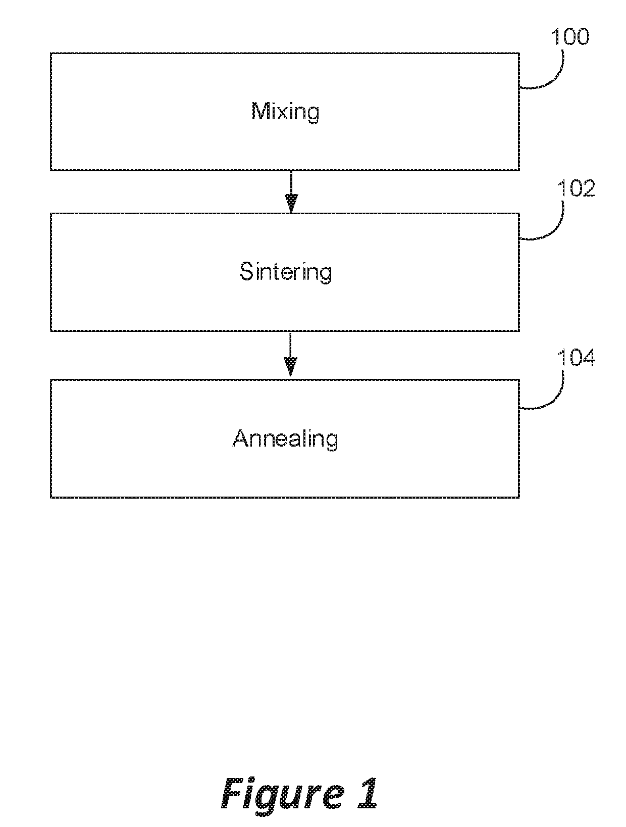
[0056]FIG. 1 is a flowchart illustrating a method of fabricating a composite according to one or more embodiments of the invention.

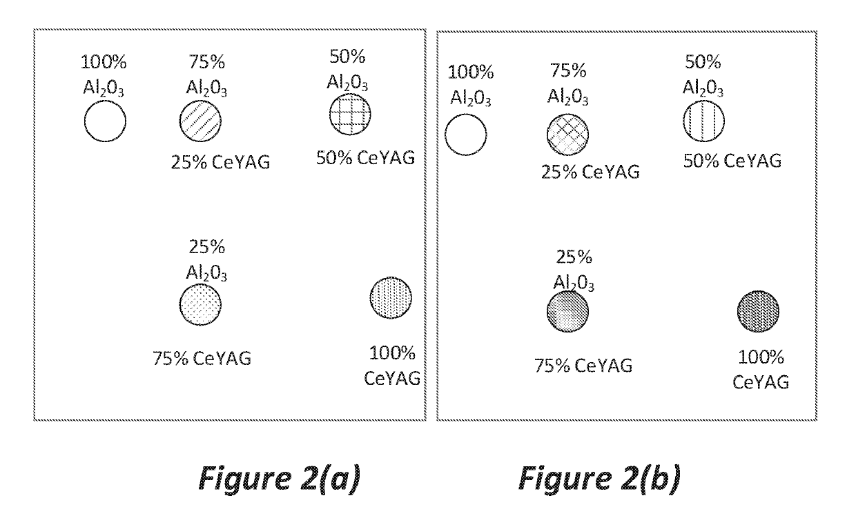
[0057]Block 100 represents preparing a mixture (mixing a phosphor and a filler to form the mixture). For the data presented herein, mixtures of commercially available Ce-doped yttrium aluminum garnet (Y3Al5O12:Ce3+, or Ce:YAG) and alpha phase alumina (α-Al2O3, Sigma Aldrich, 99.99%) were used as examples and the following mixtures of the Al2O3 (as a filler) and the Ce:YAG by weight were prepared and measured: samples of 0% Ce:YAG / 100% Al2O3, 25% Ce:YAG / 75% Al2O3, 50% Ce:YAG / 50% Al2O3, 75% Ce:YAG / 25% Al2O3, and 100% Ce:YAG / 0% Al2O3. The starting oxides (Al2O3, 99.99%) and Ce-YAG were weighed out and mixed with an alumina mortar and pestle with care taken to just mix the samples (i.e., care was taken to not grind the samples). 0.75 grams (g) of each mixture was weighed out and placed into the SPS die set with 10 mm diameter cavity with 1 mm thick grap...


PUM

PropertyMeasurementUnit
timeaaaaaaaaaa
angleaaaaaaaaaa
external quantum efficiencyaaaaaaaaaa

Abstract

A method for fabricating a composite useful in a white light emitting device, includes mixing a phosphor and a filler to form a mixture; sintering the mixture (e.g., using spark plasma sintering) to form a composite; and annealing the composite to reduce oxygen vacancies and improve optical properties of the composite. Also disclosed is a white light emitting device including a laser diode or light emitting diode optically pumping the phosphor in the composite to produce white light. The composite fabricated using the method (and having. e.g., at most 50% phosphor by weight) can (1) reduce an operating temperature of the phosphor by 55 degrees, (2) increase an external quantum efficiency (e.g., by at least 15%) of the white light emitting device, and (3) result in color points and quality of the white light that is equal to or improved, as compared to without the filler.

Description

CROSS REFERENCE TO RELATED APPLICATIONS[0001]This application claims the benefit under 35 U.S.C. Section 119(e) of the following co-pending and commonly-assigned application:[0002]U.S. Provisional Patent Application No. 62 / 368,614 filed on Jul. 29, 2016, by Clayton J. Cozzan and Ram Seshadri, entitled “Ce:YAG / Al2O3 COMPOSITES FOR LASER-EXCITED SOLID-STATE WHITE LIGHTING,” Attorney's Docket No. 30794.622-US-P 1 (UC Ref. 2016-99P); which application is incorporated by reference herein.STATEMENT REGARDING FEDERALLY SPONSORED RESEARCH AND DEVELOPMENT[0003]This invention was made with Government support under Cooperative Agreement No. DE-AR0000671 awarded by the U.S. Department of Energy's Advanced Research Projects Agency-Energy (ARPA-E). The Government has certain rights in this invention.BACKGROUND OF THE INVENTION1. Field of the Invention[0004]The present invention is related to the fabrication of a composite comprising a phosphor for use in solid state lighting.2. Description of the...

Claims


Application Information

Patent Timeline
Patent Type & Authority Applications(United States)
IPC IPC(8): C09K11/02F21K9/64F21K9/68C09K11/77C04B35/44C04B35/10C04B35/645
CPCC09K11/02C04B2235/6567F21K9/68C09K11/7774C04B35/44C04B35/10C04B35/645F21Y2115/10F21Y2115/30C04B2235/3222C04B2235/662C04B2235/666C04B2235/6562F21K9/64C04B2235/3217H01L31/055H01L33/502H05B33/14H05B33/20C04B35/117C04B2235/3225C04B2235/3229C04B2235/6565C04B2235/6582C04B2235/664C04B2235/77C04B2235/80C04B2235/9646H01L33/501H01L2933/0041Y02E10/52C04B2235/6581C04B2235/9607Y02B20/00
Inventor COZZAN, CLAYTON J.DENBAARS, STEVEN P.SESHADRI, RAM
Owner RGT UNIV OF CALIFORNIA
Why Eureka
Try Eureka