Refrigerant compressor

Active Publication Date: 2019-09-05
SECOP GMBH
View PDF0 Cites 5 Cited by
  • Summary
  • Abstract
  • Description
  • Claims
  • Application Information

AI Technical Summary

Benefits of technology

[0029]Through this, an optimum noise suppression and, at the same time, an especially stable attachment of the sp

Problems solved by technology

In each case according to the operating mode of the refrigerant compressor, the movement of the piston and the crankshaft causes vibrations, which are transferred via the elastic mounting of the compres

Method used


Image

  • Refrigerant compressor
  • Refrigerant compressor

Examples


Embodiment Construction

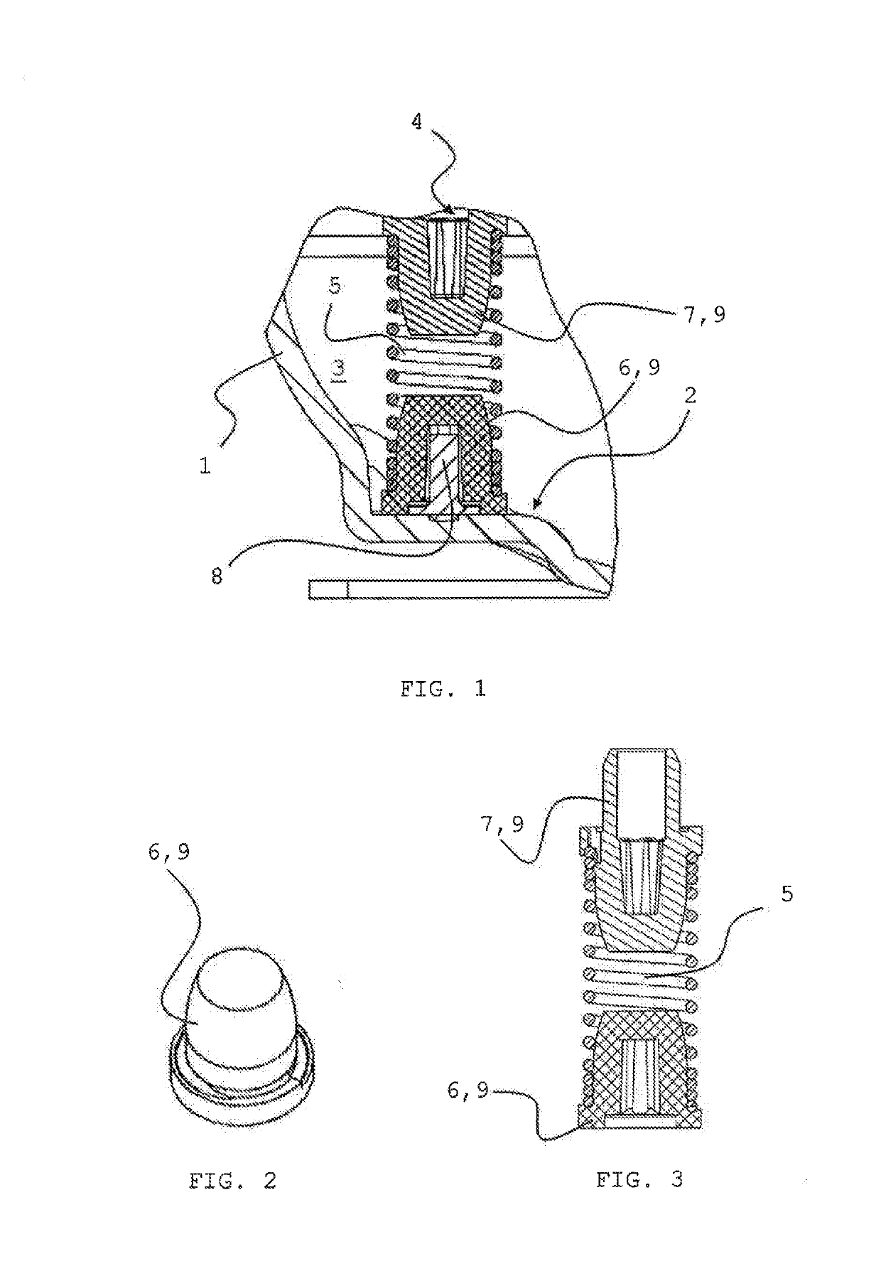
[0036]FIG. 1 shows a detail of a compressor housing 1 of a refrigerant compressor according to the invention in a sectional view.

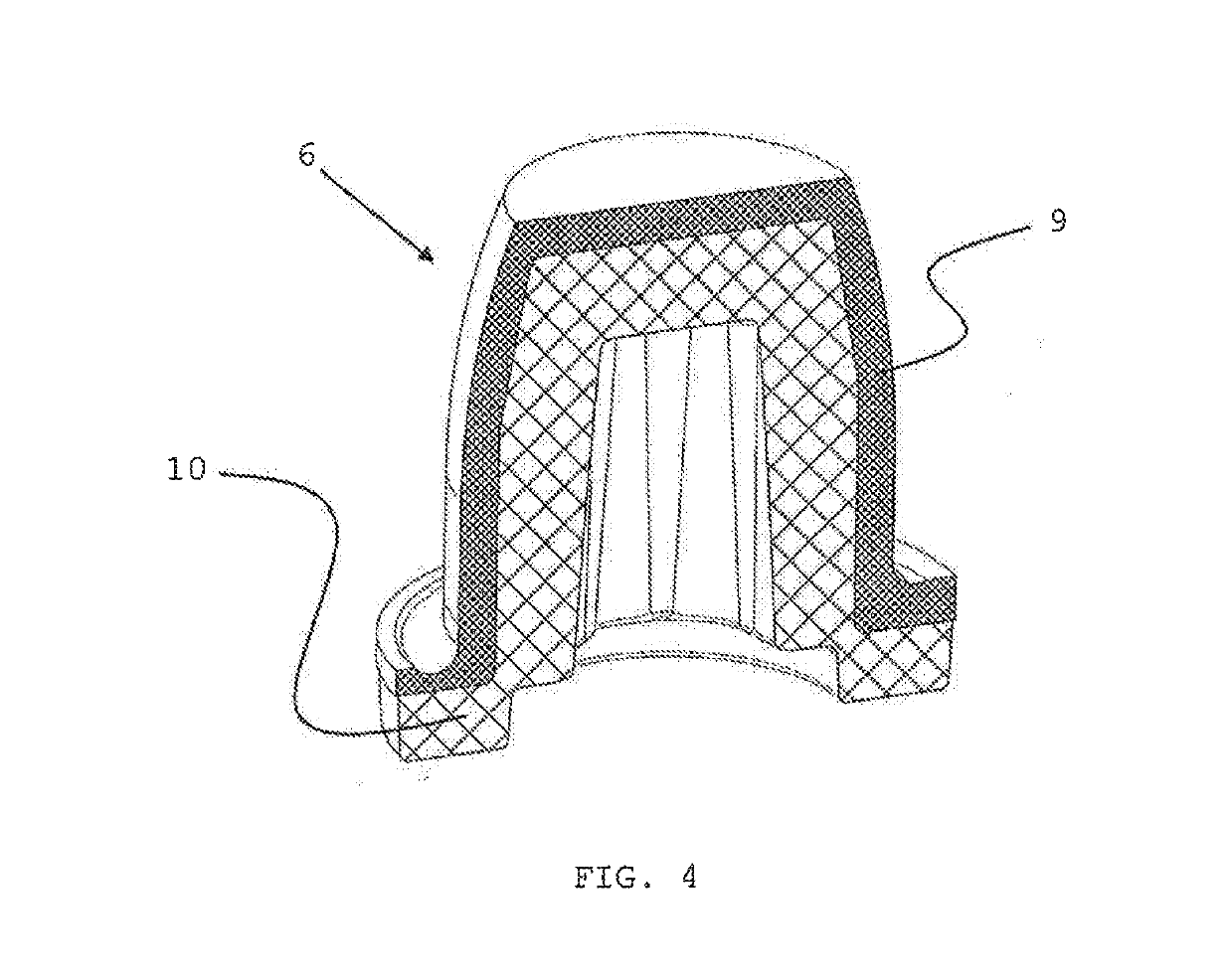
[0037]The plane of the section runs centrally through a first damping element 9 in the form of a mounting element 6, a spring element 5 in the form of a helical screw, via which a compressor-motor unit 4 of the refrigerant compressor disposed in an internal space 3 of the refrigerant compressor is elastically mounted on an inner side 2 of the compressor housing 1, and through a second damping element 9 in the form of a connecting element 7, wherein the spring element 5 is connected to the compressor-motor unit 4 via the connecting element 7 and to the inner side 2 of the compressor housing 1 via the mounting element 6.

[0038]In the embodiment example of the refrigerant compressor according to the invention that is shown, the compressor-motor unit 4 is mounted not via just the one spring element 5 but rather via a total of four spring elements 5, each in the...


PUM

PropertyMeasurementUnit
Fractionaaaaaaaaaa
Fractionaaaaaaaaaa
Fractionaaaaaaaaaa

Abstract

The invention relates to a refrigerant compressor, comprising a compressor housing (1) that am be hermetically capsuled, and a compressor-motor unit (4) arranged in the housing interior (3) of the compressor housing (1), which is elastically mounted on an inner side of the compressor housing (1) by way of at least one spring element (5), wherein at least one damping element (9) made of an elastomer is provided, in order to damp the transmission of vibrations caused by the compressor-motor unit (4) to the compressor housing (1). The at least one damping element (9) is made of an elastomer tied is softer compared to polyamide (PA), polybutylene terephthalate (PBT), ethylene chlorotrifluoroethylene (ECTFE).

Description

FIELD OF THE INVENTION[0001]The invention concerns a refrigerant compressor comprising a hermetically sealable compressor housing and a compressor-motor unit disposed in an interior part of the compressor housing, said unit being elastically mounted on an inner side of the compressor housing via at least one spring element, wherein at least one damping element made of an elastomer is provided in order to dampen the transfer of vibrations produced by the compressor-motor unit to the compressor housing.PRIOR ART[0002]Refrigerant compressors having a compressor-motor unit that is elastically mounted on an inner side of a hermetically sealable compressor housing via one or more spring elements are well known.[0003]The operation of such refrigerant compressors can essentially be outlined as follows: A crankshaft driven by an electric motor causes a piston that is movably mounted in a cylinder block to make a periodic linear movement between two dead points of the cylinder, so that in an ...

Claims


Application Information

Patent Timeline
IPC IPC(8): F04B39/00
CPCF04B39/0044F04B39/127B29C67/246F04B39/12F04B39/00F04B53/003
Inventor STEEN, HELGEBRUNE, FABIANNIELSEN, SVEN-ERIC
Owner SECOP GMBH
Why Eureka
Try Eureka