

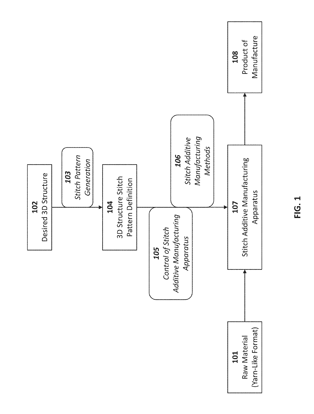
Additive manufacturing system using interlinked repeating subunits
a manufacturing system and additive technology, applied in the field of additive manufacturing systems, can solve the problems of increasing the cost of the average user, affecting so as to improve the quality of products, reduce printing errors, and reduce waste products
- Summary
- Abstract
- Description
- Claims
- Application Information
AI Technical Summary
Benefits of technology
Problems solved by technology
Method used
Image

Examples
example 1
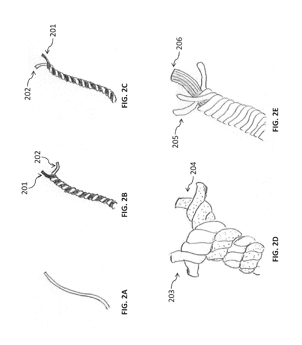
Producing Structures Using Novel Input Material
[0227]Turning now to FIGS. 4A through 4J, the figures depict an example of a three-dimensional structure and a method of making such a structure from interlinked subunits of input material 101 discussed above. For example, as shown in FIG. 4A, first stitch 401a is formed from input material 400. As shown in FIG. 4A, first stitch 401a forms a starter loop to begin an additive manufacturing process with input material 400. FIG. 4B shows a corresponding cuboid representation of first stitch 401a, with the cuboid representation referred to as reference numeral 401b. The cuboid representation of FIG. 4B shares the same ratio of length, width, and height as the yarn-like structure from FIG. 4A; however, the cuboid representation depicts how equal-sized subunits can be used to generate a predetermined structure using the techniques discussed herein. The following figures discussed include both yarn-like representations and cuboid representatio...
example 2
of Method of Producing Structures Using Novel Input Material
[0232]Moreover, FIGS. 5A-5N provide an extension of the interlinking method as discussed above, forming an exemplary 3-by-3 array with working yarn material 500 spanning the x-direction and y-direction, and extending to the z-direction when a second layer is formed. Similar to FIGS. 4A-4J above, the method shown in FIGS. 5A-5J include 509a, which is the ninth stitch of the bottom layer of the array, and active loop 510a which begins to form the second layer of the array, as shown in FIGS. 5A-5D (with cuboid 509b representing ninth stitch 509a; cuboid 510b representing active loop 510a; 511a representing a new active loop after a pull-through is performed on 510a; cuboid 511b representing new active loop 511a; direction 599 depicting the direction of stitching; and arced lines 598 joining interlinked subunits, similar to the description of the subunits in the paragraphs above). Similarly, FIGS. 5E-5J depict the continued int...
example 3
ve Method of Producing Structures Using Novel Input Material
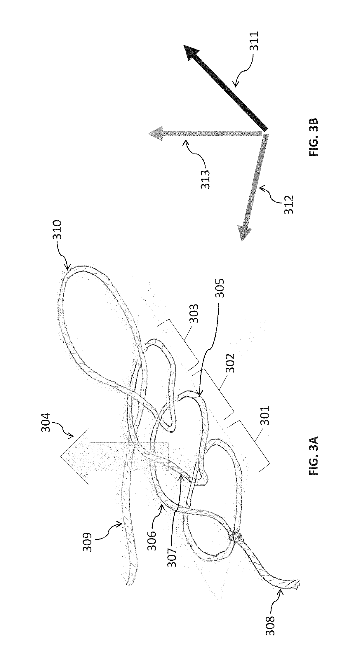
[0236]As an example of the vast realm of possibilities of methods of interlinking subunits, FIG. 6A depicts interlinking formations using counter-clockwise stitching, in contrast of the clockwise stitching shown in FIG. 3A and explored in FIGS. 4-5. In the counter-clockwise stitching shown in FIG. 6A, the yarn of the bottom loop of a stitch 601 transitions to form the right loop 602 of the next stitch before transitioning to form the left loop 603 of that next stitch, thereby producing a counter-clockwise stitch. Clockwise and counter-clockwise stitches can both be incorporated or combined into a product of manufacture. Moreover, another variation for stitch formation is that the left loop and right loop of a stitch can be twisted together such that the left loop moves towards the right of the stitch and vice versa. This twist can be accomplished by twisting the active loop before it is set into a stitch. The twist can be a...
PUM
| Property | Measurement | Unit |
|---|---|---|
| degrees of freedom | aaaaa | aaaaa |
| structure | aaaaa | aaaaa |
| volume | aaaaa | aaaaa |
Abstract
Description
Claims
Application Information