
Fluid treatment systems and methods of using the same

Pending Publication Date: 2019-10-03
ETHONUS INC
View PDF8 Cites 3 Cited by
  • Summary
  • Abstract
  • Description
  • Claims
  • Application Information

AI Technical Summary

Benefits of technology

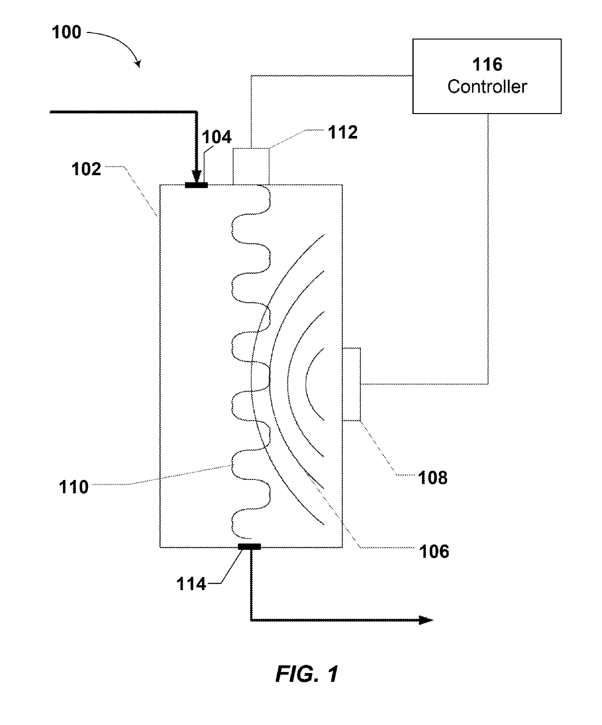
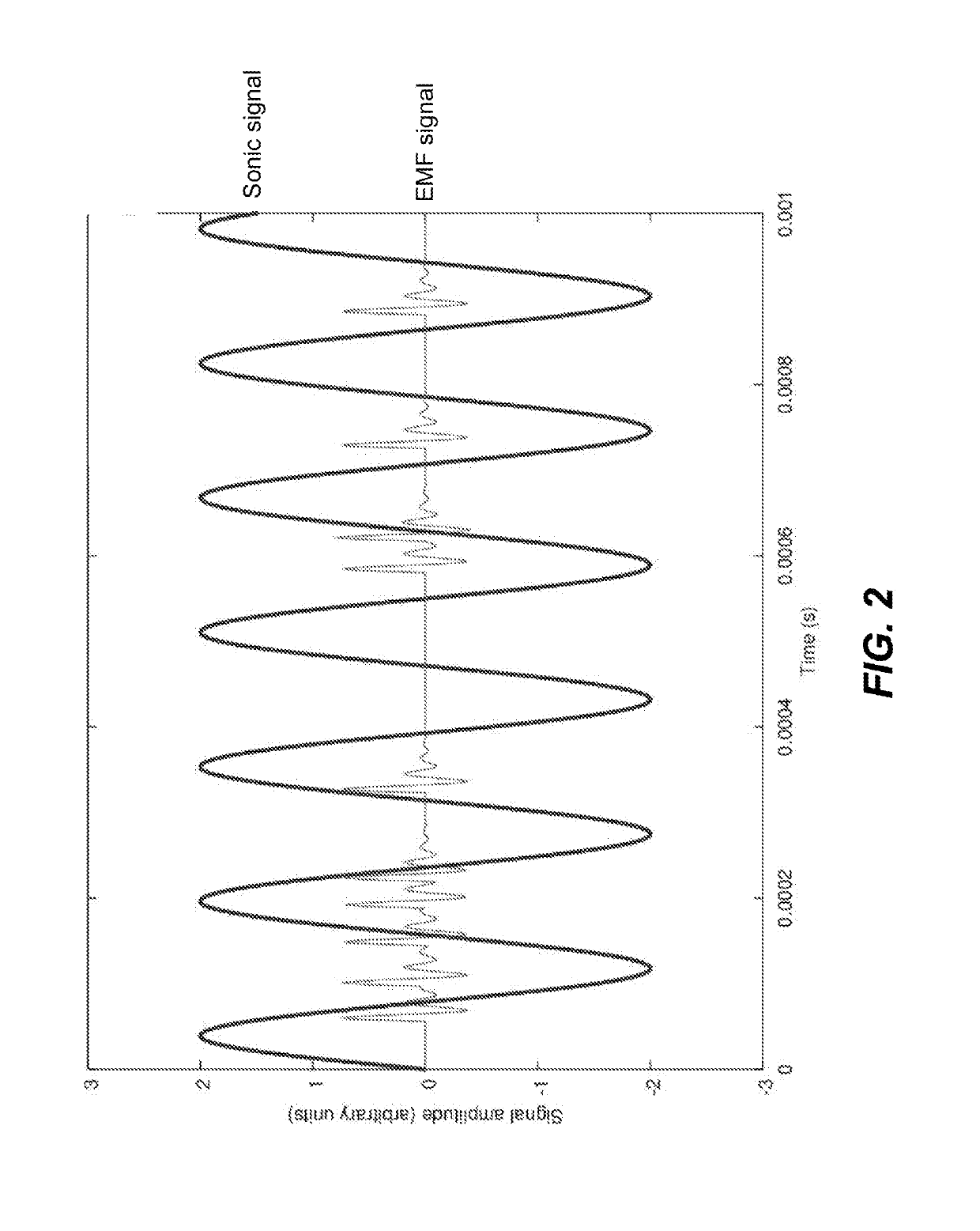
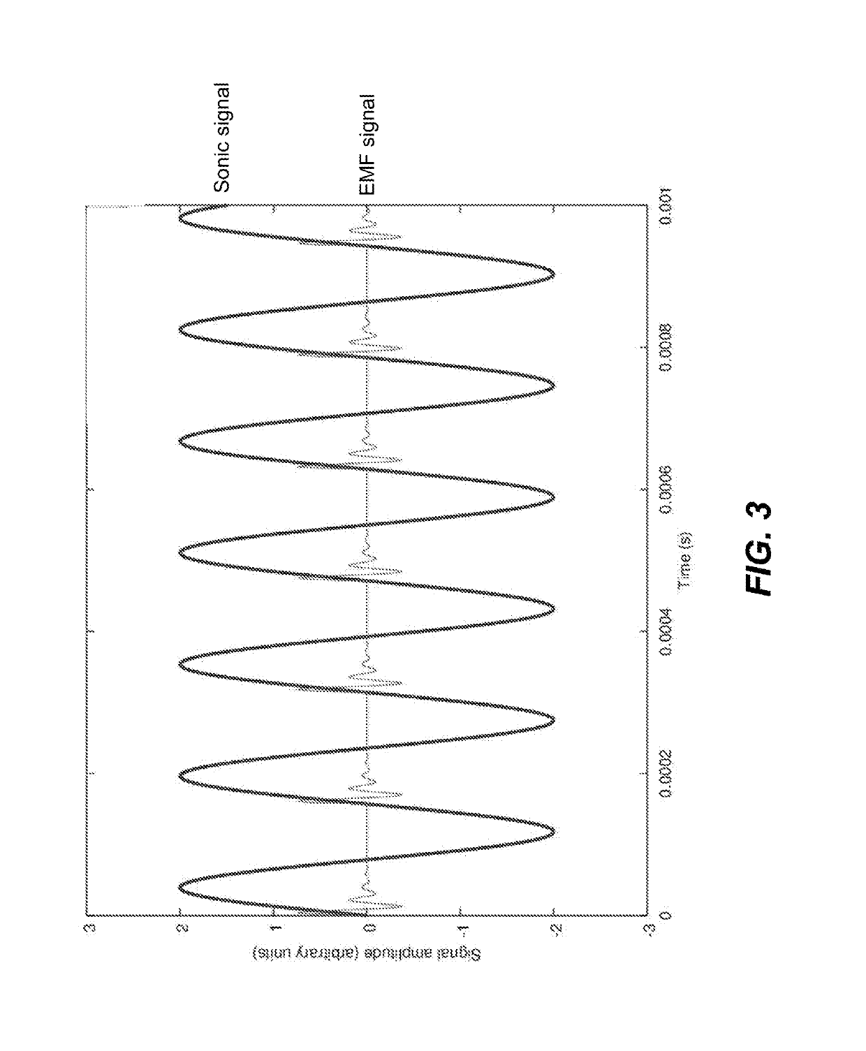
This patent describes a system that uses sonic energy and EMF signals to treat water in a vessel. The system includes multiple AWG units and a water treatment device with a sonic energy generator and an EMF generator. The system also includes a structure to increase mixing of ambient air near the first AWG unit. A controller is used to independently control the multiple AWG units and the water treatment device. The technical effects include more effective mixing of sonic energy and EMF signals, which leads to improved treatment results.

Problems solved by technology

However, there are few fluid treatment mechanisms that do not, require the use of chemicals, which may be disadvantageous (e.g., in the case of drinking water), that may be used to treat a variety of fluids having a variety of contaminants with minimal adjustment, and / or that are space and energy efficient given the volume of fluid that may be treated.

Method used


Image

  • Fluid treatment systems and methods of using the same
  • Fluid treatment systems and methods of using the same
  • Fluid treatment systems and methods of using the same

Examples


example 1

[0145]A large scale AWG platform includes a plurality of small AWG units and a plurality of large AWG units. The small AWG units are efficient at high humidity levels (e.g., 80% or better relative humidity), but are vow inefficient at low humidity levels (e.g., below 50% relative humidity). The large AWG units are not as efficient at high humidity as the small units, but can generate appreciable amounts of water at a relative humidity lower than 50%. In such case, the control system may operate the large units continuously in order to base-load the generation of water, while activating the small units when the humidity exceeds 50% to gain the advantage of their efficiency at this point. Depending on several factors (e.g., power costs, etc.), the control system may activate the small units when the humidity exceeds 80%. By utilizing a combination of AWG units, the control system is able to maximize the generation of water while minimizing the energy required, as compared to using str...

example 2

[0160]A model was created to show the impact of the placement of a large scale AWG platform on regional weather patterns based on forecast models. The model used the existing, open-source Weather Research and Forecasting 3.0 (WRF) program, which was developed over several, years to model and predict the behavior of the atmosphere from the Earth's surface (including the Planetary Boundary Layer) and through the troposphere and higher elevations based on historical and current weather and geographic data, and is maintained by the National. Center for Atmosphere Research. The model was used to simulate the weather patterns over the southern United States, using a 100×100 grid with 10 km spacing. Initial conditions for weather data were taken from the National Weather Service.

[0161]The base case represents the NLA and was calculated using weather with initial conditions and forecasting 48 hours in the future, with time increments of 30 seconds. The modified cases, with the large scale A...


PUM


Abstract

A fluid treatment system that includes a sonic energy generator and an electromagnetic field, generator is described herein. The fluid treatment system may include a controller that independently controls the sonic energy generator and the EMF generator while in use. Also described herein are methods of treating a fluid including applying a sonic signal to at least, a portion of the fluid, and applying an electromagnetic field signal to at least the portion of the fluid by a direct conductive path. Methods of treating water that has been extracted by an atmospheric water generator unit using such a fluid treatment system are also described herein.

Description

BACKGROUNDTechnical Field[0001]Embodiments of the disclosure are generally directed to fluid treatment systems that use sonication and conductive electromagnetic fields, as well as methods of using the same.Description of the Related Art[0002]A variety of fluid treatment mechanisms are known in the art, including chemical treatments (e.g., advanced oxidation processes (AOP)), sonication, filtration, and application of electromagnetic fields. Fluid treatment systems typically include one or more treatment mechanisms that are applied to the same volume of fluid in serial. In other words, a first treatment will be used on a volume of fluid in a first location and then the fluid travels to a second location, where the volume of fluid is treated with a second treatment.[0003]However, there are few fluid treatment mechanisms that do not, require the use of chemicals, which may be disadvantageous (e.g., in the case of drinking water), that may be used to treat a variety of fluids having a ...

Claims


Application Information

Patent Timeline
IPC IPC(8): C02F1/36B01D53/26C02F1/48
CPCC02F1/484C02F2201/48B01D53/265C02F2209/005C02F1/36C02F1/02C02F1/28C02F1/32C02F1/42C02F1/441C02F1/442C02F1/444C02F1/445C02F1/46C02F1/52C02F1/66C02F1/70C02F1/722C02F1/725C02F1/78C02F2101/006C02F2101/36C02F2103/001C02F2103/10C02F2209/008Y02W10/37Y02E10/30A61L2202/14B06B1/04C02F1/485C02F2209/00A61L2/025B08B3/12E03B3/28
Inventor FLECKNER, KARENNEYLON, MICHAEL
Owner ETHONUS INC
Learn More