
Composite glass pane

a technology of composite glass and glass, applied in the field of laminated safety glasses and glasses, can solve the problems of low risk of injury to persons behind the glass pane caused by flying glass fragments, beneficial for limited applications, and is usually not possible, and achieves finely crumbled fracture patterns, high torsional rigidity, and high scratch resistance.

Pending Publication Date: 2019-10-10
SCHOTT AG
View PDF0 Cites 3 Cited by
  • Summary
  • Abstract
  • Description
  • Claims
  • Application Information

AI Technical Summary

Benefits of technology

The patent describes a new type of laminated glass pane that is strong and durable, but also maintains good view through the glass. The glass is made from a special glass powder, which can be easily produced and reshaped. This innovation solves the issue of small splinters caused by impacts and also ensures high torsional rigidity and a good view even in a damaged state. Overall, this new laminated glass pane is cost-efficient, lightweight, and safe for use in automobiles.

Problems solved by technology

In this case, the risk of injury to persons behind the pane caused by flying glass fragments is low.
Actually, this is only beneficial for limited applications.
However, this is usually not possible due to significantly different viscosity characteristics of the employed glasses that are known from the prior art.
In the few cases in which glasses are selected which can be shaped simultaneously, this implies drawbacks in stiffness and in the parameters CS and DoL, and / or requires a complex and costly, mostly multi-step process of solidification.
Another drawback is that very high temperatures are necessary for the thermal shaping, especially in the case of the aluminosilicate glasses which are most frequently used in the prior art as glasses that can be toughened chemically.
In the event of fracturing, this finely crumbled fracture pattern will strongly impede the view in the vehicle outside, and moreover increases the risk that small splinters might detach with the result of an increased risk of injury to vehicle passengers.
Furthermore, a depletion in lithium will occur.
Optical distortion of a glass sheet is a result of varying thickness across the width of the glass sheet, for example caused by the drawing process, for example due to slight contamination at the drawing slit or when the glass sheet is removed from the tin bath.

Method used


Image

  • Composite glass pane
  • Composite glass pane
  • Composite glass pane

Examples


Embodiment Construction

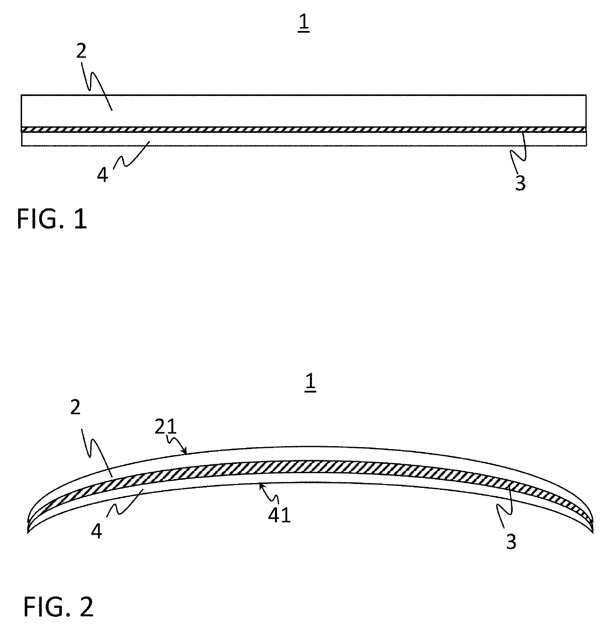
[0088]FIG. 1 is a schematic view, not drawn to scale, of a laminated glass pane 1 comprising a first glass sheet 2, a polymeric layer 3 disposed between and bonding the first glass sheet 2 to the second glass sheet 4, and finally the second glass sheet 4.

[0089]More generally, however, without being limited to the exemplary embodiment illustrated here, it is also possible for the laminated glass pane to comprise more than two glass sheets. For example, this may be the case when particularly high mechanical loads are expected and, accordingly, a particularly high strength of the laminated glass pane is desired.

[0090]The polymeric layer 3 has a thickness between at least 0.5 mm and at most 1.7 mm. It may be provided in the form of a film, for example a film comprising EVA and / or polyvinyl butyral, or in the form of a layer comprising a plurality of films, or a multilayer film. But it is also possible to form the polymeric layer in situ, by applying monomers to one of the two glass shee...


PUM

PropertyMeasurementUnit
thicknessaaaaaaaaaa
thicknessaaaaaaaaaa
thicknessaaaaaaaaaa

Abstract

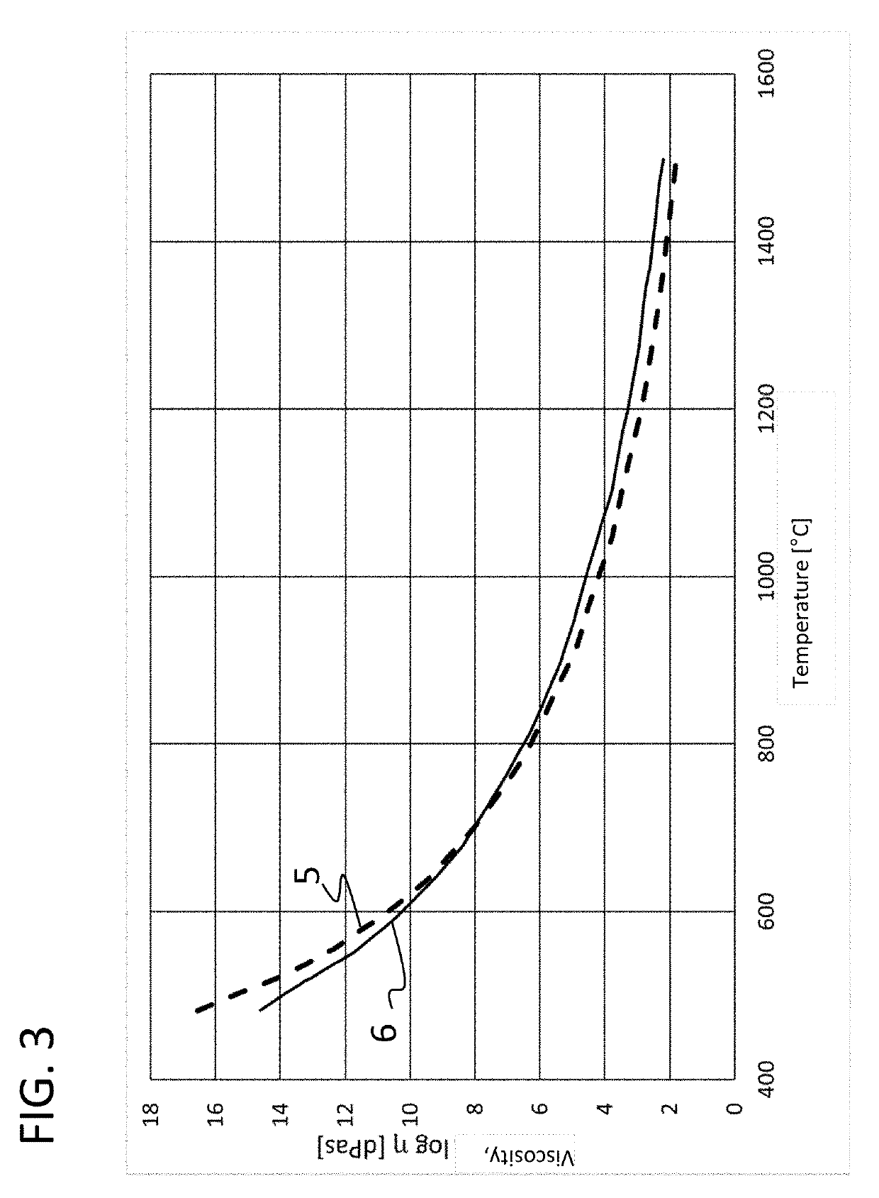
A laminated glass pane is provided that includes a first glass sheet, a polymeric layer having a thickness between at least 0.5 mm and at most 1.7 mm, and a second inner glass sheet which has a thickness of at least 0.3 mm and at most 1.5 mm and is made of a lithium aluminum silicate glass. The polymeric layer is disposed between the at least two glass sheets. Furthermore, the glasses of the first and the second glass sheets are matched so that the temperatures at which the two glasses of the first and second glass sheets have the same viscosity in the viscosity range between 107 dPa·s and 1010 dPa·s differ from each other only by a maximum of 50° C.

Description

CROSS REFERENCE TO RELATED APPLICATIONS[0001]This application is a continuation of International Application No. PCT / EP2017 / 081380 filed Dec. 4, 2017, which claims benefit under 35 USC 119(a) of German Application No. 10 216 125 488.6 filed Dec. 22, 2016, the entire contents of all of which are incorporated herein by reference.BACKGROUND1. Field of the Invention[0002]The invention relates to laminated safety glasses and to glasses which are suitable for use in a laminated safety glass.2. Description of Related Art[0003]Laminated safety glasses have been state of the art for many years and are known to be a composite of at least two glass sheets with a film disposed therebetween. In the case of an impact of an external force on the laminated pane, the special structure of laminated safety glass ensures that, although individual or all glass sheets may break, the laminated pane will resist the external force in such a way that no item will pass through and in some applications even an...

Claims


Application Information

Patent Timeline
Patent Type & Authority Applications(United States)
IPC IPC(8): B32B17/10C03C3/083
CPCB32B2551/00C03C3/083B32B2329/06B32B17/10045B32B2571/00B32B2329/04B32B17/10137C03C3/087C03C3/093C03B18/02B32B3/30B32B17/10036B32B17/10119B32B2315/08B32B2605/006C03B17/064C03C21/002C03B23/023B32B3/02B32B3/26B32B3/263Y10T428/24777
Inventor ALKEMPER, JOCHENKLIPPE, LUTZDIETRICH, RÜDIGER
Owner SCHOTT AG
Learn More