
Intelligent electricity meter system with light wallet

a smart electricity meter and wallet technology, applied in the integration of power network operation systems, instruments, sustainable buildings, etc., can solve the problems of large system challenges, randomness and stiffness at the load side, and load is unaffected in normal case completely, so as to achieve economic feasibility of microgrids and meet the demand for energy internet big data

Inactive Publication Date: 2019-10-24
HEPU TECH DEV BEIJING CO LTD
View PDF4 Cites 14 Cited by
  • Summary
  • Abstract
  • Description
  • Claims
  • Application Information

AI Technical Summary

Benefits of technology

The present invention aims to solve problems in the prior art regarding electricity meters. It allows for peer-to-peer electricity transactions and the collection, transaction, and recording of distributed wind photovoltaic and storage battery energy. Additionally, it facilitates demand for energy Internet big data. The invention enables the implementation of distributed electricity generation and storage, as well as bi-directional metering of electric energy production and consumption. This enables the efficient monitoring and control of electricity usage in a scattered intelligent microgrid. The use of intelligent electricity meters acts as evidence of transaction charges, making the microgrid economically more feasible.

Problems solved by technology

At a power supply side, with a high renewable energy capacity, a random fluctuation of the power supply brings about great challenges to the system.
At a load side, due to a change in electric power consumption structures and a rapid development of electromobiles, the randomness and stiffness at the load side are continuously getting serious.
However, the current centralized grid control mode and the manner of the power grid collecting electricity meter data uniformly are facing great challenges in the future.
Even if the user uses a lowest-level device, the load is unaffected completely in normal case.
However, the real-time electricity transaction or the peer-to-peer electricity transaction cannot be implemented by the current electricity meter technology.

Method used


Image

  • Intelligent electricity meter system with light wallet
  • Intelligent electricity meter system with light wallet

Examples


first embodiment

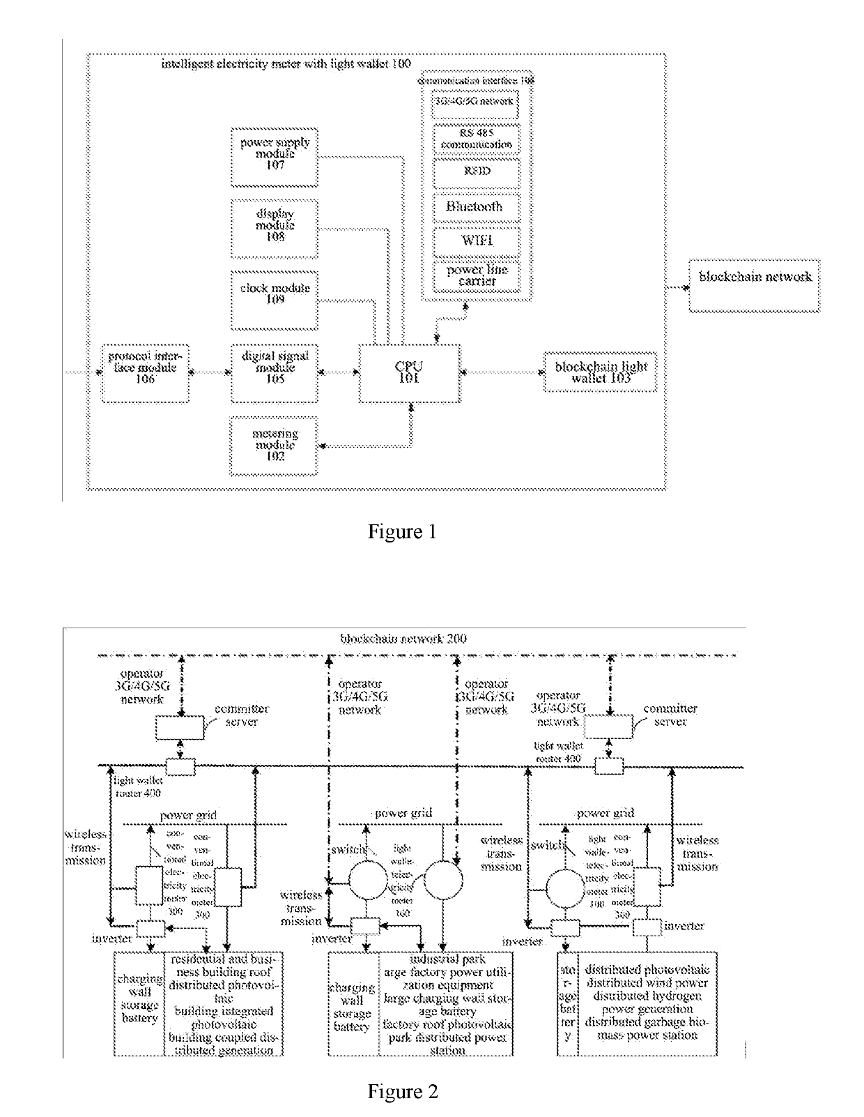
[0056]With reference to FIGS. 1 and 2, the present invention provides an intelligent electricity meter system with a light wallet, including: a CPU 101, a metering module 102, a blockchain light wallet module 103 and a communication module 104, wherein

[0057]the CPU 101 is used for processing and operating data in the intelligent electricity meter 100, and controlling data exchange;

[0058]the metering module 102 is connected with the CPU 101, for unidirectionally or bi-directionally metering electric quantity;

[0059]the blockchain light wallet module 103 is connected with the CPU 101, and performs data interaction with the CPU 101;

[0060]the communication module 104 is wirelessly or wiredly connected to the CPU 101, the metering module 102, and the blockchain light wallet module 103 respectively, for implementing the data transmission between the metering module 102 and the blockchain light wallet module 103, and the data transmission in the blockchain network 200.

[0061]In the present e...

second embodiment

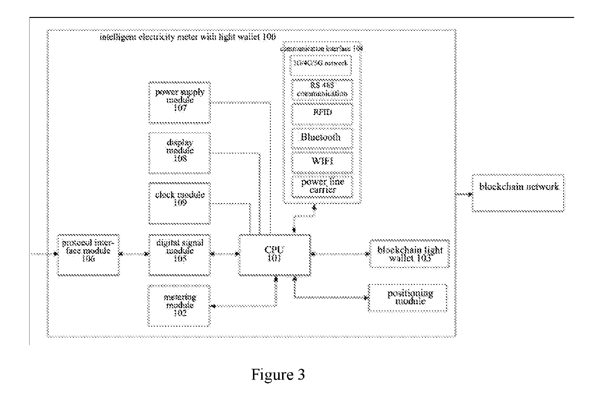
[0090]With reference to FIG. 3, the present embodiment differs from the first embodiment in that the intelligent electricity meter 100 according to the second embodiment further includes a positioning module, connected with the CPU 101, for positioning the intelligent electricity meter 100.

[0091]When the intelligent electricity meter according to the present embodiment is running, the geographic position information of the blockchain node is obtained by the positioning module positioning the intelligent electricity meter 100, which realizes the geographic position informatization of the entire intelligent power grid, thereby laying a foundation for the optimal rationalization of the peer-to-peer automatic electricity transaction of the blockchain. That is, in the blockchain intelligent contract, it can be appointed that in case of the same quotation, preferably, the electricity transaction between the two nearest nodes geographically is facilitated, which leads to the lowest electri...

third embodiment

[0094]The present embodiment provides an intelligent electricity meter system, including a conventional intelligent electricity meter 300 and a blockchain router 400, wherein the conventional intelligent electricity meter 300 is provided therein with the CPU 101, the metering module 102 and the communication module 104, and the blockchain router 400 is provided therein with the blockchain light wallet module 103 and the communication module 104.

[0095]In the present embodiment, each module of the intelligent electricity meter system has the same function and operation manner as in the first embodiment, and they are not repeated herein.


PUM


Abstract

The present invention discloses an intelligent electricity meter system with a light wallet, including a CPU, a metering module, a blockchain light wallet module and a communication module. By using a blockchain light wallet module, the present invention solves the problems that the electricity meter in the prior art cannot implement the peer-to-peer electricity transaction, and electric quantity collection, transaction and recording of the distributed wind photovoltaic and storage battery, and the demand for the energy Internet big data cannot be met. The distributed electricity generation and storage as well as the bi-directional metering of electric energy production and electricity consumption of an electricity user are implemented, such that the electricity quantity of a scattered intelligent microgrid may be metered, transacted and recorded. The distributed electricity generation side and utilization side make the microgrid more feasible economically by taking the intelligent electricity meter as an evidence of transaction charge.

Description

CROSS-REFERENCE TO RELATED APPLICATIONS[0001]The present application claims the benefit of priority to Chinese patent application No. 201810345219.3, titled “INTELLIGENT ELECTRICITY METER SYSTEM WITH LIGHT WALLET”, filed with the Chinese State Intellectual Property Office on Apr. 18, 2018, the entire disclosure of which is incorporated herein by reference.FIELD OF THE INVENTION[0002]The present invention relates to the field of intelligent electricity meter and blockchain technologies, in particular to an intelligent electricity meter system with a light wallet.BACKGROUND OF THE INVENTION[0003]Due to uniqueness of an electric power system, an ultra large network, i.e. power grid, is formed by nature from electricity generation, transmission and distribution to utilization. At its one end, there are traditional energies such as fire coal, fuel gas, nuclear power and hydropower as well as distributed renewable energies such as wind and light, and at the other end, there are millions o...

Claims


Application Information

Patent Timeline
Patent Type & Authority Applications(United States)
IPC IPC(8): G06Q20/36G01D4/00H04L9/06H04L9/32G01R11/56
CPCG06Q20/363G01D4/002H04L9/0618H04L9/3247H04L2209/56G01R11/56H04L2209/38H04L9/3236G06Q20/0655G06Q20/145G06Q20/3829G07F15/003G07F15/06G06Q20/127G06Q20/223G06Q20/367Y04S50/12Y04S20/30Y02B70/34Y02B90/20H04L9/50
Inventor CUI, HUAYANG, YUSENXU, BOTAN, ZHICHEN, HUI
Owner HEPU TECH DEV BEIJING CO LTD
Learn More