Multimodality 2D To 3D Imaging Navigation

Active Publication Date: 2019-10-24
GENERAL ELECTRIC CO
View PDF7 Cites 5 Cited by
  • Summary
  • Abstract
  • Description
  • Claims
  • Application Information

AI Technical Summary

Benefits of technology

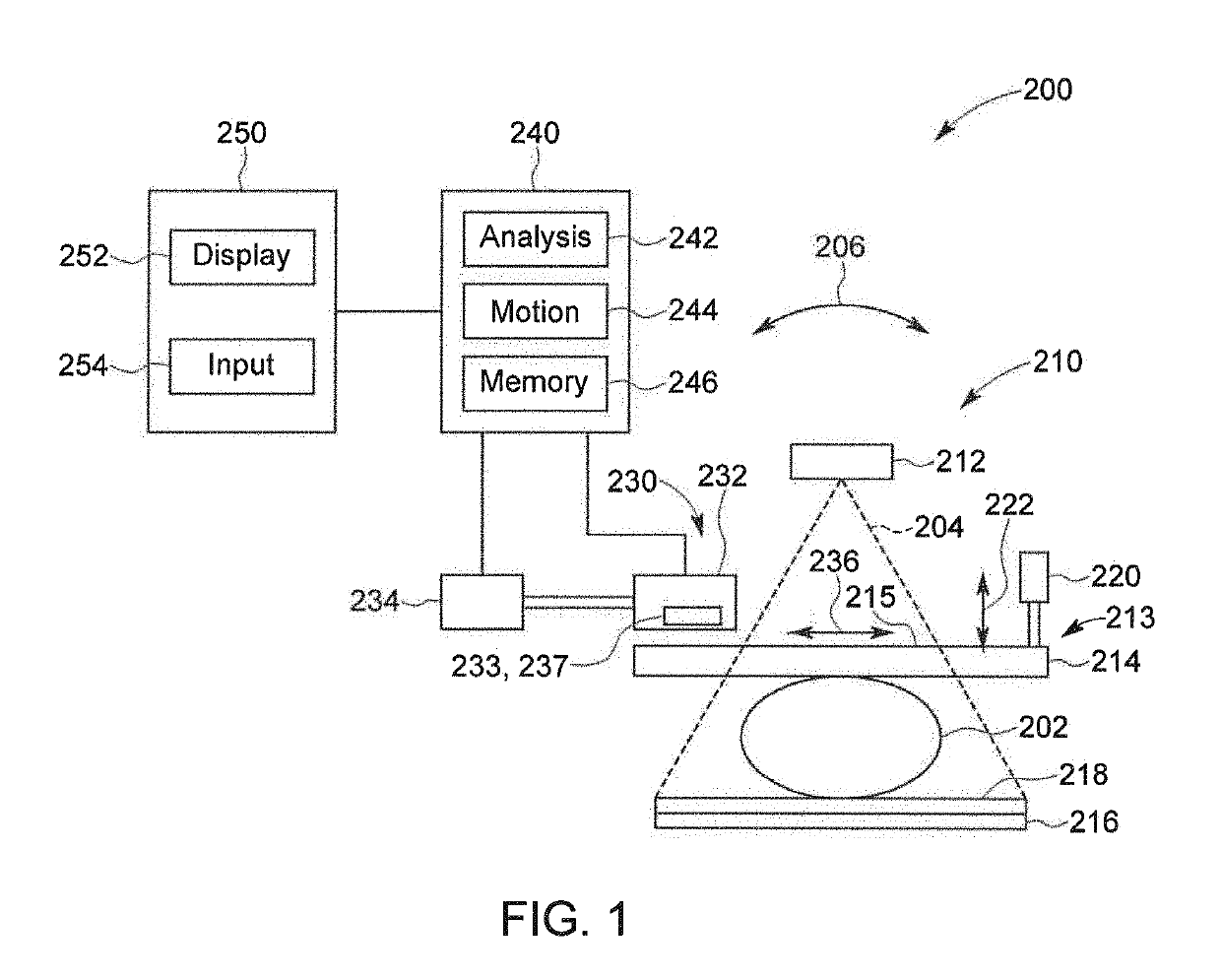
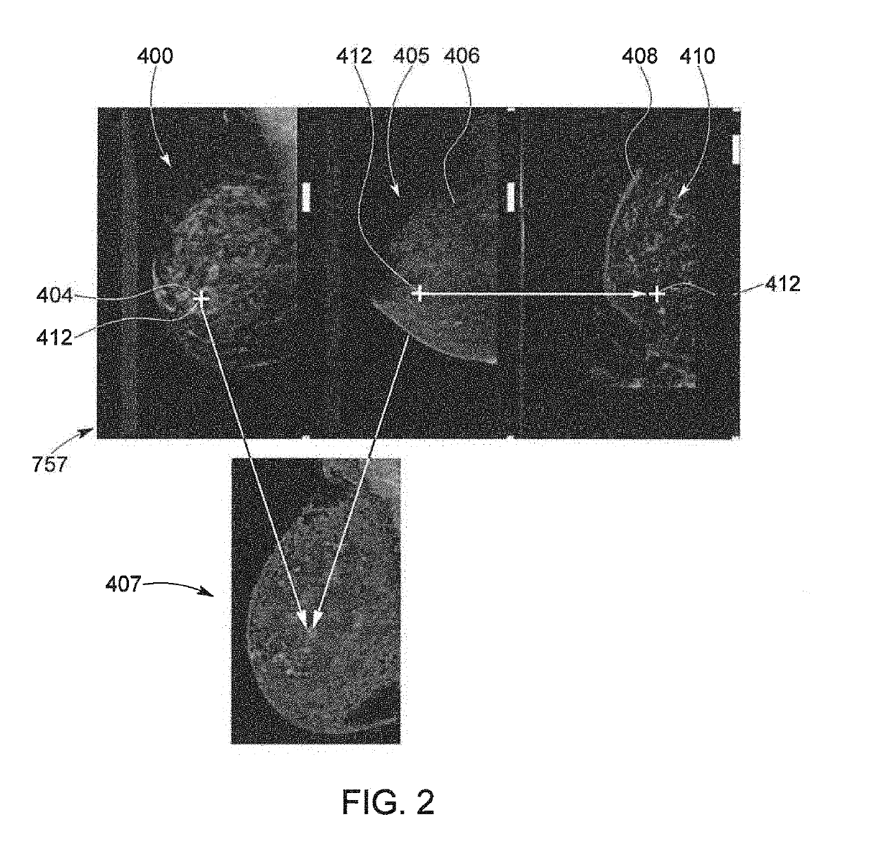
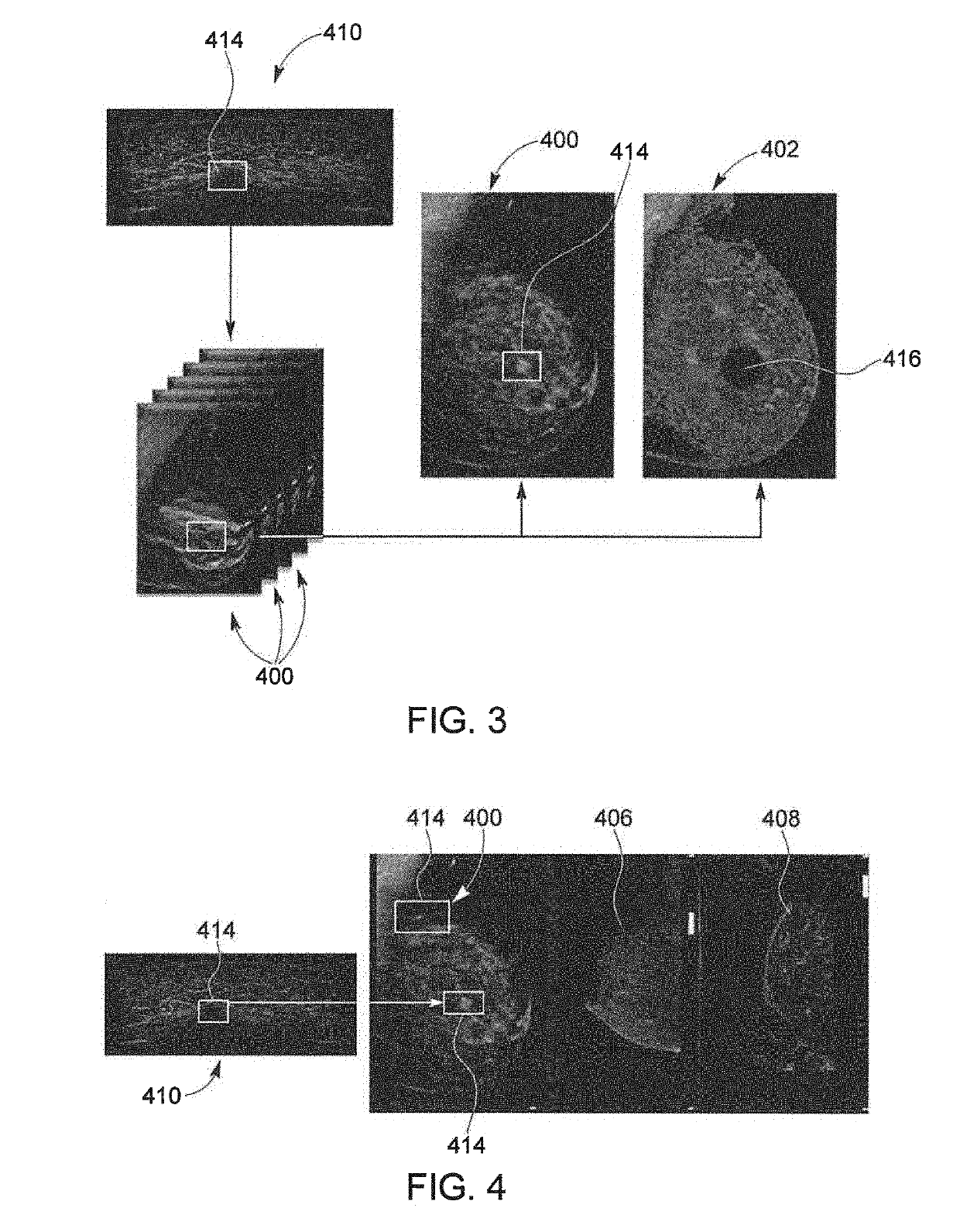
[0011]There is a need or desire for a system and method for the detection of ROIs in images obtained of a breast or other tissue of a patient significantly improves the speed and accuracy of navigation between multimodality 2D and 3D images. In the system and method, images of the tissue are obtained in a 3D DBT acquisition to generate a synthetic 2D image of the imaged tissue and in a 3D, e.g., ultrasound or MRI, image acquisition. The 2D image generation process creates a synthetic 2D image that each embed a navigation map correlating pixels in the 2D image to sections of the 3D ultrasound

Problems solved by technology

Such rescheduling typically involves a delay of days or even weeks between exams.
This amount of time can lead to patient anxiety and concern between the examinations.
Further, because the exams are conducted at separate visits, and also because upright positioning and compression is typically used for mammographic X-ray exams and supine positioning is used for ultrasound or prone for MRI, it is very difficult to co-register the X-ray image and ultrasound image such that the radiologist or other practitioner can view the same areas imaged using the different modalities.
Present techniques for performing ultrasound examinations of the breast have additional drawbacks, such as the time associated with such examinations.
In practice, the manual method practiced by radiologists is quite tedious and prone to error.
However, variations in the images obtained in the mammography and ultr

Method used


Image

  • Multimodality 2D To 3D Imaging Navigation
  • Multimodality 2D To 3D Imaging Navigation
  • Multimodality 2D To 3D Imaging Navigation

Examples


Example

[0022]Various embodiments will be better understood when read in conjunction with the appended drawings. To the extent that the figures illustrate diagrams of the functional blocks of various embodiments, the functional blocks are not necessarily indicative of the division between hardware circuitry. Thus, for example, one or more of the functional blocks (e.g., processors, controllers or memories) may be implemented in a single piece of hardware (e.g., a general purpose signal processor or random access memory, hard disk, or the like) or multiple pieces of hardware. Similarly, any programs may be stand-alone programs, may be incorporated as subroutines in an operating system, may be functions in an installed software package, and the like. It should be understood that the various embodiments are not limited to the arrangements and instrumentality shown in the drawings.

[0023]As used herein, an element or step recited in the singular and proceeded with the word “a” or “an” should be ...


PUM


Abstract

A system and method for the detection of ROIs in images obtained of a breast or other tissue of a patient significantly improves the speed and precision/accuracy of navigation between multimodality 2D and 3D images. In the system and method, images of the tissue are obtained in a DBT acquisition to generate a synthetic 2D image of the imaged tissue and in a 3D, e.g., ultrasound, image acquisition. The 2D image generation process creates a synthetic 2D image that embed a navigation map correlating pixels in the 2D images to sections of the 3D ultrasound volume, such as via a registration between the 3D ultrasound volume and a 3D volume created using the DBT image data. When a synthetic 2D image is reviewed, an ROI on the 2D image is selected and the system will additionally present the user with the section of the 3D volume containing that ROI.

Description

BACKGROUND OF THE DISCLOSURE[0001]The present disclosure relates to the field of combined 2D and 3D imaging and to a method and system for processing 2D and 3D imaging data for improving navigation through the imaging data.[0002]X-ray imaging systems have become a valuable tool in medical applications such as for the diagnosis of many diseases. As standard screening for breast cancer mammography 2-dimensional (2D) x-ray images are taken across the entire breast tissue. These known 2D mammograms are limited by tissue superimposition. That is to say, lesions may be masked by the tissue above or underneath, or normal structures may mimic a lesion. In order to minimize limitations of standard 2D-mammography caused by tissue superimposition, digital breast tomosynthesis using digital receptors has been developed.[0003]Current tomosynthesis systems employ at least one x-ray tube, which is moved, e.g., in an arc, above a stationary detector. In digital breast tomosynthesis (DBT) the volume...

Claims


Application Information

Patent Timeline
IPC IPC(8): G06T7/00G06T15/08G06T11/00
CPCG06T15/08G06T2200/04G06T2207/10112G06T7/0012G06T2207/30068G06T2207/10084G06T11/003G06T2207/10088G06T2207/10081A61B34/20A61B2034/2065A61B2034/2063A61B6/025A61B6/463A61B6/502A61B6/5247A61B6/5235A61B6/5223A61B6/469A61B6/481A61B8/0825A61B8/085A61B8/4218A61B8/4281A61B8/54A61B8/5207
Inventor BERNARD, SYLVAINDAVIS, CYNTHIA
Owner GENERAL ELECTRIC CO
Why Eureka
Try Eureka