Soon after the cap is applied there is a build-up of pressure as the boiling
Nitrogen expands but is unable to escape the sealed container.
However, lighter weight containers for noncarbonated products can collapse when stacked unless special handling requirements are satisfied.
As the
nitrogen disperses immediately upon injection, however, the process for controlling accurate dosing is limited.
Additionally, handling
nitrogen systems can be costly and dangerous.
However, as the nitrogen is dosed prior to sealing there is loss of some of the nitrogen
dose prior to sealing.
Plastic bottles need to be pressurized at all line speeds, and if control over the exact pressure achieved inside a container is compromised then the speed of the
system will also be compromised in order to correctly pressurize each container.
In the case of a hot filled beverage, an insufficient
dose results in the container being sealed at
ambient pressure and possessing little ability to pressurize the container following sealing.
This is not attractive for the
consumer.
Additionally, the dosing process becomes even more difficult to control in the hot fill environment, particularly at fast line speeds.
It will disperse much more quickly prior to capping or sealing leaving the consistency of
dose even more uncertain.
A stoppage in the line is therefore more damaging to consistency of dose.
For this reason, containers are often overdosed as a precautionary measure, and this is still not ideal.
The dosing equipment can control the
liquid nitrogen up to the dosing point, but as already now disclosed it cannot control the
liquid nitrogen's behavior once it has been dosed into the container.
Using this method, any variation in head-space volume due to variations in fill level would cause under and over pressurized containers.
Problems of uniform pressurization remain as a major problem with
liquid nitrogen dosing, especially when used with hot-fill beverages.
Therefore, in prior art it is not considered feasible to provide cooling simultaneously with the capping of filled containers, or the temperature of the contents is compromised before it may be utilized for internal sterilization purposes.
Not only would there be substantial risk in introducing
foreign matter into the container prior to sealing, but the temperature of the product would be compromised and the
efficacy of the
pasteurization model would be corrupted.
Once the liquid cools down in a capped container, however, the volume of the liquid in the container reduces, creating a vacuum within the container.
This liquid shrinkage results in vacuum pressures that pull inwardly on the side and end walls of the container.
This in turn leads to deformation in the walls of plastic bottles if they are not constructed rigidly enough to
resist such force.
Even with such substantial displacement of vacuum panels, however, the container requires further strengthening to prevent
distortion under the vacuum force.
The liquid shrinkage derived from liquid cooling, causes a build-up of
vacuum pressure.
The more difficult the structure is to deflect inwardly, the more vacuum force will be generated.
In prior art proposals, a substantial amount of vacuum may still be present in the container and this tends to distort the overall shape unless a large, annular strengthening ring is provided in horizontal, or transverse, orientation typically at least a ⅓ of the distance from an end to the container.
A problem exists when locating such transversely oriented panels in the container side-wall, or end-wall or base region, even after vacuum is removed completely from the container when the liquid cools down and the panel is inverted.
This
refrigeration provides further product contraction and in containers with very little sidewall structure, so-called ‘glass look-a-like’ bottles, there may therefore be some
panelling that occurs on the containers that is unsightly.
This situation is very hard to engineer successfully, however, as it depends on utilising a larger headspace in order to compress at base
inversion time, and it is less desirable to introduce a larger headspace to the container than is necessary in order to retain product quality.
While it is desirable to have the liquid level in the container drop, to avoid spill when opened by the
consumer, it has been found that providing too much
positive pressure potential within the base may cause some product spill when the container is opened, particularly if at ambient temperatures.
Headspace contains gases that in time can damage some products or place extra demands on container
structural integrity.
A problem in prior art is the amount of
Oxygen present in the headspace gas, typically as a 21% percentage of air.
Filling and sealing a rigid container at elevated temperatures can create significant vacuum forces when excessive headspace gas is also present.
In hot filling of beverages in PET containers, the
thermal stability of the material of the container also constitutes a challenge.
PET has a low
glass transition point of approximately 75 degrees C. When the headspace of a container is pressurized while the liquid contents are above about 70 degrees C., the container walls are subjected to particularly damaging forces.
However, even with containers such as described in the abovementioned PCT specifications where there is little residual
vacuum pressure, the neck finish of the container is still required to be very thick in order to withstand the temperature of fill.
In nitro-dose applications there is significant container
distortion when the PET material is above about 70 degrees C. to 75 degrees C. due to the high level of
nitrogen pressure within the container.
The container effectively grows in volume and the base is disfigured and unstable.
Also for example, structures in the sidewall, such as ribbing, may be similarly affected causing uncontrolled container growth and distortion.
This distortion causes a
weakness in any strengthening structures and is very undesirable.


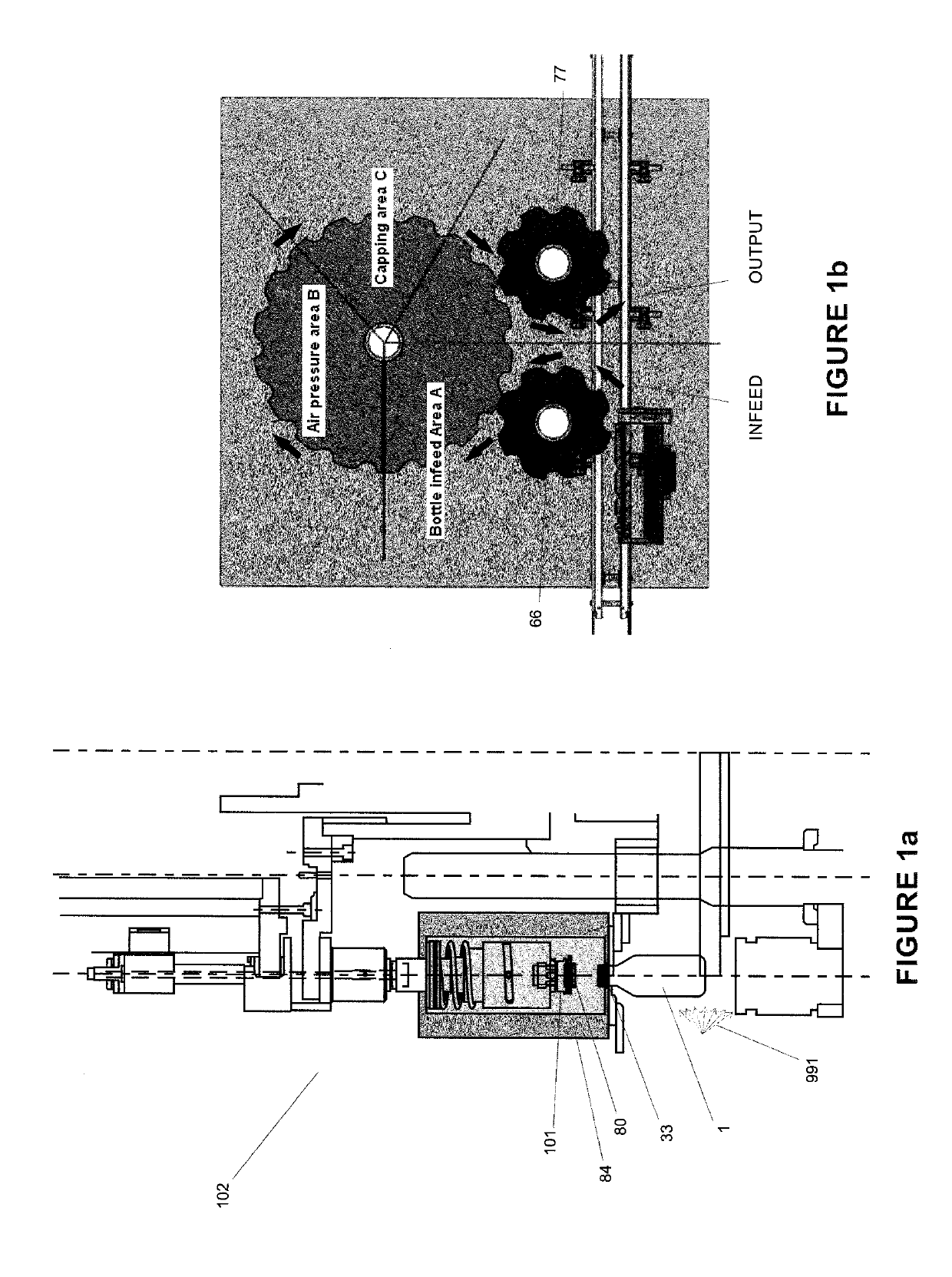
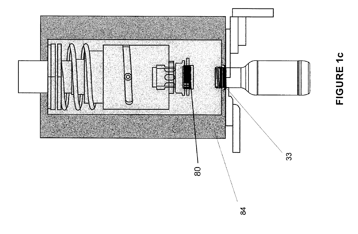