Organ-on-chip platforms with reduced fluid volume

a technology of organs and chips, applied in the field of microfluidic devices, can solve the problems of ending experiments, unable to accept viable drugs, limited translation of animal models to human physiology, etc., and achieve the effect of effectively sealing or attaching scaffolds and being easy to install

Pending Publication Date: 2019-10-31
MASSACHUSETTS INST OF TECH
View PDF4 Cites 5 Cited by
  • Summary
  • Abstract
  • Description
  • Claims
  • Application Information

AI Technical Summary

Benefits of technology

[0024]Also provided are means for effectively sealing or attaching scaffolds to wells in the organ-on-chip platforms. Examples of attachment means include an elastomeric retaining ring, bi-stable spring, angled ring and lip, external screw mount with tube or spring, snap fit with flexure, deflecting beam, tilting ring, wave spring, or retaining ring with elastomer. The attac

Problems solved by technology

In the long and costly process of developing a new drug, an important challenge is screening drugs for toxicity and efficacy before clinical trials.
Animal models are limited in their translation to human physiology, which has caused failures in clinical trials and may cause viable drugs to be rejected (Dehne, et al., Future Science OA, vol.
While low circulating volume is desirable, there are challenges with oxygenating an open-well system at low volumes.
A wide channel is susceptible to height fluctuations which allows fluid to be stored in the oxygenator while the cells run dry, ending the experiment.
Lack of bidirectional flow prevents efficient oxyg

Method used


Image

  • Organ-on-chip platforms with reduced fluid volume
  • Organ-on-chip platforms with reduced fluid volume
  • Organ-on-chip platforms with reduced fluid volume

Examples


example 1

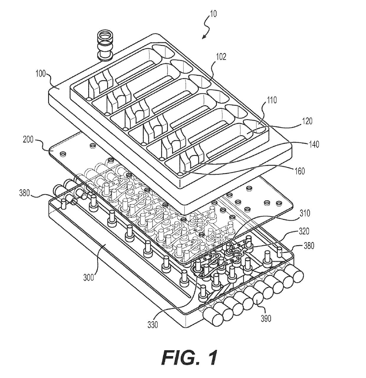
r Design and Testing—Conical SLA Resin Spiral and PSU Spiral Breadboards, and Conical and Elongated PSU Spiral Oxygenators as Revision 1 and Revision 2 Oxygenators

[0317]Materials, Methods, and Results

[0318]Designing an open-well system at very low volumes requires careful attention to surface tension effects, which can be difficult to predict by modeling alone. The design process relied heavily on quickly iterating prototypes and breadboard models to test individual components of the system.

[0319]The corner flow oxygenation concept was selected for implementation based on the anticipated performance relative to the requirements and anticipated development / manufacturing time as expressed in Table 1. Integration of the oxygenator into the platform itself with no crevices or interfaces requiring adhesive is a significant advantage for sterilization, cell compatibility, and usability.

[0320]Two surrogates were used in the process: (1) a 1% bovine serum albumin (BSA) solution in phosphate...

example 2

2 Oxygenator

[0331]Materials and Methods

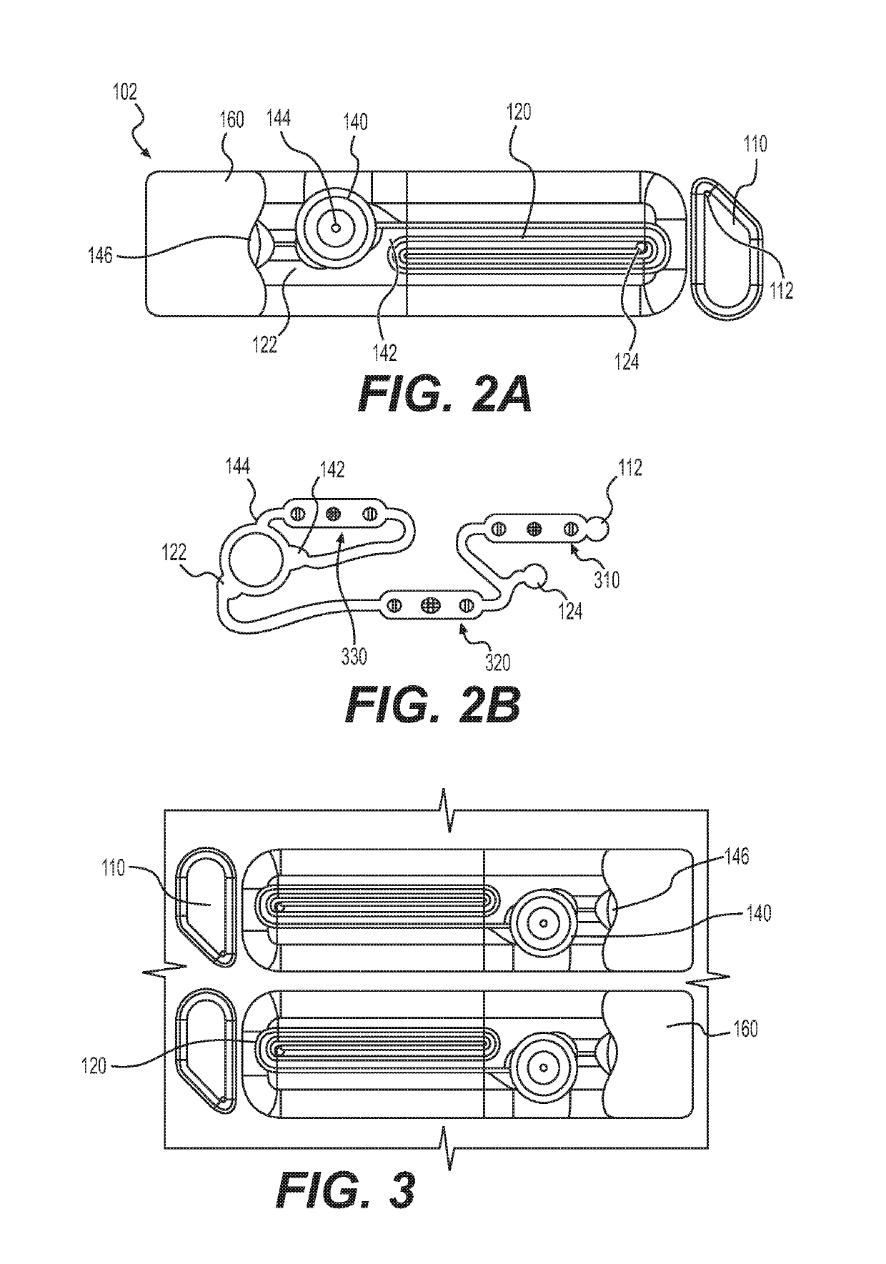
[0332]After further SLA validation of the wetting characteristics of an elongated spiral oxygenator without guidance channels, the revision 2 platform was machined from polysulfone (FIG. 3). This oxygenator was 4 mm in height, half the height of Rev 1 oxygenator (8 mm), and one fourth the height of the PSU spiral breadboard (16 mm). Each lane was surrounded by a barrier to prevent cross-contamination. The flat surfaces were sloped so as to empty to the end of the oxygenator, and the radius at the base of the barrier walls was large enough to prevent fluid accumulation.

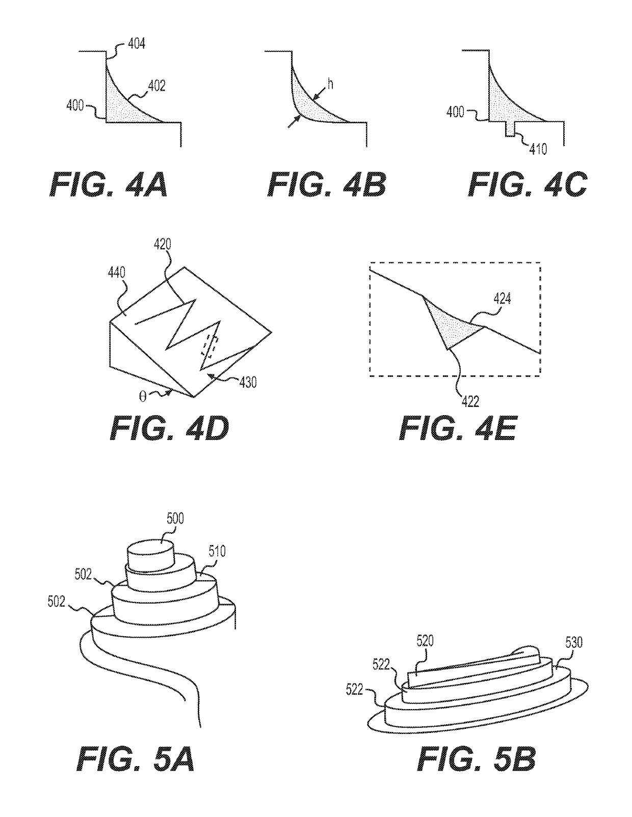
[0333]To oxygenate the media through a free air-liquid interface while constraining the fluid path and limiting the volume that can collect in the oxygenator, a spiral oxygenator was developed that captured the fluid in the corner of a spiral cut into the hydrophilic polysulfone, as shown in FIG. 3. The corner served to limit the maximum thickness of fluid that oxygen must diffuse...

example 3

Oxygenator Performance

[0337]Materials and Methods

[0338]Analytical Modeling

[0339]An analytic modeling for predicting oxygenator performance and highlighting its dependence on various physical parameters was used as follows. The model was compared to measured data.

[0340]The performance of the oxygenator can be described by an efficiency φ, the oxygenation potential:

φ≡Cb-CaCsat-Ca,Equation2.2

where the oxygen concentration difference of inlet (Ca) and outlet (Cb) is normalized by the maximum possible oxygenation, that is when the outlet is at saturation Csat. This parameter allows comparison of oxygenators across experiments, where the input concentration is likely to vary, and is independent of cell oxygen consumption activity. Further, it can be directly measured with a probe each at the oxygenator inlet and outlet.

[0341]The analysis that follows expresses this oxygenation potential in terms of relevant parameters of the system: flow rate Q, diffusion depth h, air-liquid interface are...


PUM


Abstract

Organ-on-chip platforms with reduced fluid volumes include circulating fluid volumes of below 1000 μL, preferably about 500 μL or less. The platforms are adjustable for culturing cells with varied oxygen demand at various seeding densities. The platforms include at least one lane, wherein each lane includes at least one cell culture well, at least one oxygenator for fluid oxygenation, and a pump system containing at least one pump per lane. The oxygenator may include a separate fluid path for oxygenating the fluid, which allows controlling and measuring the oxygen concentration in the fluid, shortening the diffusion length, and passively diffusing oxygen. Provided are also different configurations for the oxygenator, fluid circulation in the platforms, attachment means for securing scaffolds to culture wells, and pneumatic plates.

Description

CROSS-REFERENCE TO RELATED APPLICATIONS[0001]This application claims the benefit of and priority to U.S. Provisional Application No. 62 / 645,080 filed Mar. 19, 2018, which is incorporated herein by reference in its entirety.STATEMENT REGARDING FEDERALLY SPONSORED RESEARCH[0002]This invention was made with Government support under Grant No. UH3-TR000496 awarded by the National Institutes of Health. The Government has certain rights in the invention.FIELD OF THE INVENTION[0003]The invention is generally directed to microfluidic devices for cell and tissue culture and to the subcomponents of the microfluidic devices.BACKGROUND OF THE INVENTION[0004]In the long and costly process of developing a new drug, an important challenge is screening drugs for toxicity and efficacy before clinical trials. Animal models are limited in their translation to human physiology, which has caused failures in clinical trials and may cause viable drugs to be rejected (Dehne, et al., Future Science OA, vol. ...

Claims


Application Information

Patent Timeline
IPC IPC(8): C12M1/00C12M1/12C12M1/02C12N5/071C12M3/00C12M1/34G01N33/50C12M1/32
CPCC12M21/08C12M27/00C12M23/12C12M41/34C12M25/06C12M23/44C12M25/14C12N5/0671C12M23/46G01N33/5088C12N5/0697G01N33/5008C12M29/24G01N33/5082B01L3/50273B01L2300/0858B01L2300/0861B01L2300/10B01L2400/0406B01L2400/084C12M23/16C12M27/18B01L2300/0829
Inventor RATHBONE, DANIEL RODIONTRUMPER, DAVID L.
Owner MASSACHUSETTS INST OF TECH
Why Eureka
Try Eureka