
Transmission and drive system for an electric vehicle

a technology of transmission and drive system, applied in the direction of transportation and packaging, cycle, gearing, etc., can solve the problems of belt enlargement, poor practicality of existing transmission, and the most complex and cumbersome transmission applied to automobiles, etc., to achieve precise placement of fastener holes, low cost, and easy manufacturing

Active Publication Date: 2019-11-07
ZHEJIANG EASY VEHICLE
View PDF0 Cites 9 Cited by
  • Summary
  • Abstract
  • Description
  • Claims
  • Application Information

AI Technical Summary

Benefits of technology

The present invention provides a transmission system for electric vehicles, such as scooters, that is simple and space-efficient. It consists of a gear transmission and a pulley transmission mechanism, with a unidirectional transmission connected to the rear wheel for smooth coasting. The tensioning system and noise dampening plates reduce vibrational noise and provide a quieter drive. The body fixing plate provides rigidity and precise placement of fastener holes. The invention is easy and cost-effective to manufacture. Its unique design makes it suitable for a variety of vehicles, especially electric scooters.

Problems solved by technology

At present, most transmissions applied to automobiles are relatively complex and cumbersome.
Such existing transmissions are poor in practicality, unable to satisfy the requirements for a transmission for use in an electric vehicle such as an electric scooter.
That is, as belt drive systems are used, the belt can enlarge over time, either from stretching or due to wear of the inner surface of the belt causing an effective enlargement.
Without an ability to maintain a proper tension on the belt, the belt can sag resulting in inefficient performance of the drive system.
Electric drive and transmission systems, can however be relatively noisy depending on their configuration.

Method used


Image

  • Transmission and drive system for an electric vehicle
  • Transmission and drive system for an electric vehicle
  • Transmission and drive system for an electric vehicle

Examples


Embodiment Construction

[0041]In order to make the technical solutions and advantages of the embodiments of the present invention clearer, a clear and complete description of the technical solutions in the embodiments of the present invention will be made hereinafter in combination with the drawings in the embodiments of the present invention. It is apparent that the described embodiments are not all but a part of the embodiments of the present invention. Based on the embodiments of the present invention, all other embodiments obtained by those of ordinary skills in the art without creative work are within the scope of the present invention.

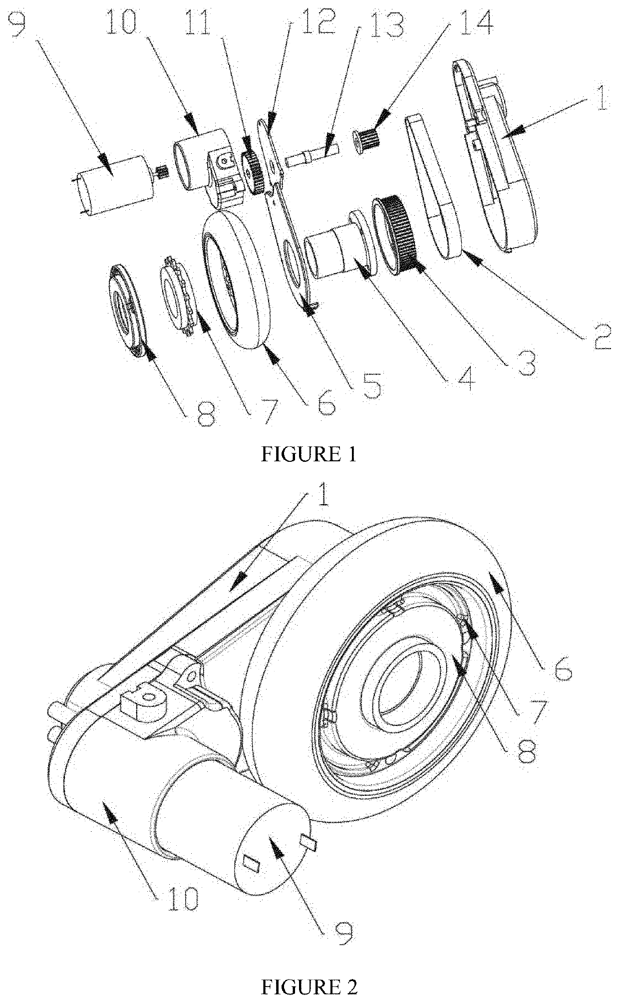
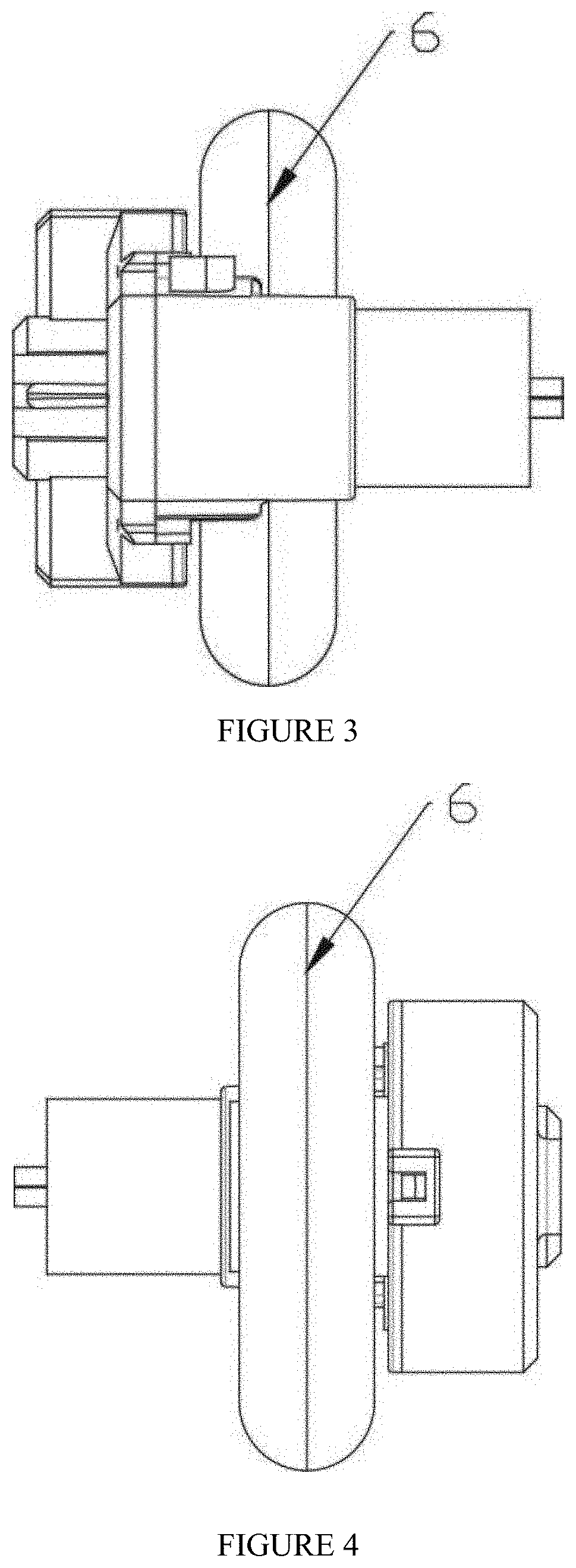
[0042]As illustrated in FIGS. 1 to 8, the embodiment of the present invention provides a transmission, an input end of the transmission being connected with a driving device, the driving device providing a power source for the transmission, an output end being connected with a rear wheel 6 for driving the rear wheel 6 to rotate, such that the vehicle moves forward; the ...


PUM


Abstract

A transmission and drive system comprises an input end connected to a driving device, an output end connected to a rear wheel, a gear transmission mechanism and a belt driven transmission mechanism. A unidirectional transmission mechanism is connected to the rear wheel with the unidirectional transmission mechanism driving the rear wheel. The transmission provides power output by the driving device, transmits power to the pulley transmission mechanism by the gear transmission mechanism, and the pulley transmission mechanism drives the rear wheel to rotate the unidirectional transmission mechanism, such that the vehicle moves forward. Noise dampening plates are provided to reduce noise emanating from the transmission. In addition, a belt tensioning system is provided to maintain consistent tension on the belt.

Description

CROSS-REFERENCE TO RELATED APPLICATIONS[0001]This application is a continuation-in-part of U.S. patent application Ser. No. 16 / 414,066 filed May 16, 2019, which is a continuation of U.S. patent application Ser. No. 15 / 678,931 filed on Aug. 16, 2017 which claims priority to Chinese Patent Application No. 201620889516.0 filed on Aug. 16, 2016, the entirety of each of which is incorporated by this reference.FIELD OF THE INVENTION[0002]The present invention relates generally to transmissions and drive systems for electric vehicles and more specifically to a transmission having a relatively small size that is light weight and capable of efficiently improving endurance mileage and energy consumption.BACKGROUND[0003]At present, most transmissions applied to automobiles are relatively complex and cumbersome. When applied to an electric vehicle, particularly for an electric scooter, a transmission needs to be small, simple, practical, have a high safety factor and reliable for operation for ...

Claims


Application Information

Patent Timeline
Patent Type & Authority Applications(United States)
IPC IPC(8): B60K17/04B62M11/02B60K17/14B62M9/02B60K7/00F16H7/08F16H7/02
CPCB62M11/02B60K2007/0061B60K7/0007F16H7/0848B62M9/02B62K2204/00F16H7/023B62K2202/00B60Y2200/91B60K17/14B60K17/043B60Y2200/126F16H7/1281F16H57/028F16H2057/02034F16H2057/02065
Inventor YU, SAMWEN, YONG
Owner ZHEJIANG EASY VEHICLE
Learn More