Systems and methods for whole cell analysis

a whole cell analysis and system technology, applied in the field of systems and methods for whole cell analysis, can solve the problems of limiting the assay throughput, reducing the flow rate of reagents, and laborious isolation of cells in each tube, and achieve the effect of reducing the flow rate and high flow ra

Active Publication Date: 2019-11-14
RGT UNIV OF MICHIGAN
View PDF0 Cites 7 Cited by
  • Summary
  • Abstract
  • Description
  • Claims
  • Application Information

AI Technical Summary

Benefits of technology

[0014]FIG. 2 shows a (a) Simulation of one branch channel with 50 Pa input pressure (unit: μm / min) (b) The tapered entrance and exit channel help maintain the constant flow rate at the upstream and midstream (c) Flow distribution across the 200 capture sites, showing higher flow rate at the midstream and lower flow rate at the upstream and downstream with ˜65% difference from peak value.

Problems solved by technology

However, those approaches have several intrinsic drawbacks.
Without a robotic system, it is very labor intensive to isolate cells in each tube, limiting the assay throughput (Liao, et al., Cancer Res., 2007, 67, 8131-8138).
Additionally, the cost for reagents adds up dramatically if the higher throughput is needed, which limits its application in research labs and clinics.
However, this technology requires large PCR reagent chamber next to the cell capture chamber for on chip PCR, which occupies a large area and limits the throughput.
However, with droplet and microwell system, it usually requires thousands of cells for analysis due to the cell loss in the single cell capture process, limiting its application for rare cell analysis.

Method used


Image

  • Systems and methods for whole cell analysis
  • Systems and methods for whole cell analysis
  • Systems and methods for whole cell analysis

Examples


example 1

Design of the Highly Parallel Channel Structure for Throughput Scaling

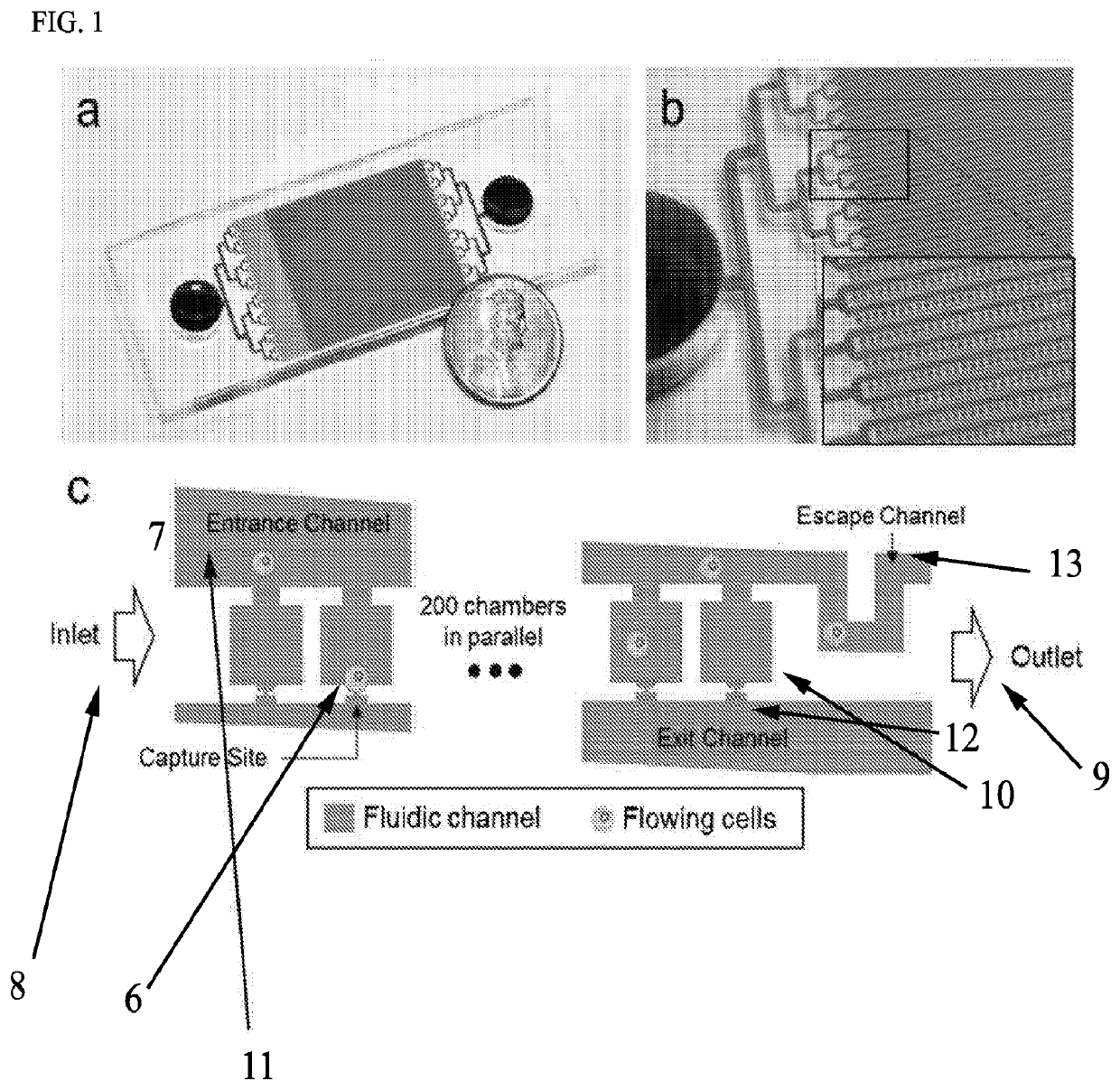
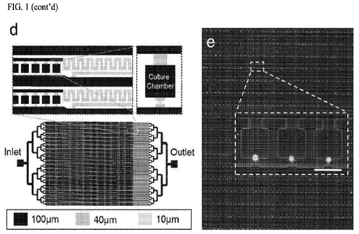
[0105]Single-cells are captured in micro-wells when they flow into the micro-wells and block the capture site. To increase the throughput, it was found that duplication of identical micro-wells into a larger array will suffer from low cell capture rate and clogging caused by non-uniformity of cell distribution between the upstream and downstream. To overcome this challenge, the scaling of the chip is achieved by engineering in two aspects. First, it was investigated how to increase more cell capture wells in each branch channel. Second, the throughput was scaled up by parallelizing the branch channels. A branch channel of 12,800-well chip is shown in FIG. 1 (c). In one design, each branch channel comprises an entrance channel and an exit channel with 200 micro-wells connected in parallel between them. After the entrance channel, a 40 μm high escape channel was added to release residual cells in the entrance channe...

example 2

Methods

Device Fabrication

[0131]The devices were made using soft-lithography fabrication process. The multi-layer layout of the chip was designed using AutoCAD 2016 (Autodesk®). The masks for photolithography were made using a mask making instrument (μPG 101, Heidelberg instruments). The mold for the flow channel was fabricated with 10 μm, 20 μm, 40 μm, and 100 μm thick SU-8 (Microchem) following the manufacturer's protocol. The valves were created using AZ®9260 (AZ Electronic Materials) with peak thickness of 15 μm and 45 μm after thermal reflow. The mold for the control channels was fabricated with 20 μm SU-8. The SU-8 mold was treated by vaporized Trichloro(1H,1H,2H,2H-perfluorooctyl) silane (448931 ALDRICH) under vacuum overnight to promote the release of cured PDMS. After coating, the mold was heated at 150° C. on a hot plate for 10 minutes. PDMS (Sylgard 184, Dow Corning) was prepared by mixing with 10 (elastomer): 1 (curing agent) (w / w) ratio, poured on flow channel molds, and...


PUM


Abstract

The present disclosure relates to systems and methods for whole cell analysis. In particular, the present disclosure relates to single cell genomic analysis (e.g., gene expression analysis.

Description

CROSS REFERENCE TO RELATED APPLICATIONS[0001]This application claims the benefit of U.S. Provisional Application No. 62 / 449,867, filed Jan. 24, 2017, which is incorporated herein by reference in its entirety.STATEMENT REGARDING FEDERALLY SPONSORED RESEARCH OR DEVELOPMENT[0002]This invention was made with government support under awards W911NF-08-2-0004 and W911NF-06-R-0006 awarded by the U.S. Army Research Lab, DARPA. The government has certain rights in the invention.FIELD OF THE DISCLOSURE[0003]The present disclosure relates to systems and methods for whole cell analysis. In particular, the present disclosure relates to single cell genomic analysis (e.g., gene expression analysis).BACKGROUND OF THE DISCLOSURE[0004]The understanding of cell gene expression not only can foster the fundamental research in cancer but also provide great potential for precision medicine by designing target medicine to specific gene expression patterns (van 't Veer, et al., Nature, 2002, 415, 530-536; Se...

Claims


Application Information

Patent Timeline
Patent Type & Authority Applications(United States)
IPC IPC(8): B01L3/00
CPCB01L2200/0668B01L2300/0893B01L2300/0864B01L2300/0883B01L3/502761B01L2400/086B01L3/502738B01L2300/0816C12M23/16C12M47/04
Inventor YOON, EUISIKCHENG, YU-HENGCHEN, YU-CHIHBRIEN, RILEYWICHA, MAX S.
Owner RGT UNIV OF MICHIGAN
Why Eureka
Try Eureka