Method for producing a textile sensor

a textile sensor and sensor technology, applied in the field of thermometers, can solve the problems of increasing the number of inserts, limiting the diameter of the conductive wire, irreversible damage of the thermometer, etc., and achieves the effects of improving the sensitivity of temperature detection, reducing the section, and increasing the length of the wir

a textile sensor and sensor technology, applied in the field of thermometers, can solve the problems of increasing the number of inserts, limiting the diameter of the conductive wire, irreversible damage of the thermometer, etc., and achieves the effects of improving the sensitivity of temperature detection, reducing the section, and increasing the length of the wir

US20190353533A1Active Publication Date: 2019-11-21KNITRONIX SRL

Image

  • Method for producing a textile sensor
  • Method for producing a textile sensor
  • Method for producing a textile sensor

Examples


Embodiment Construction

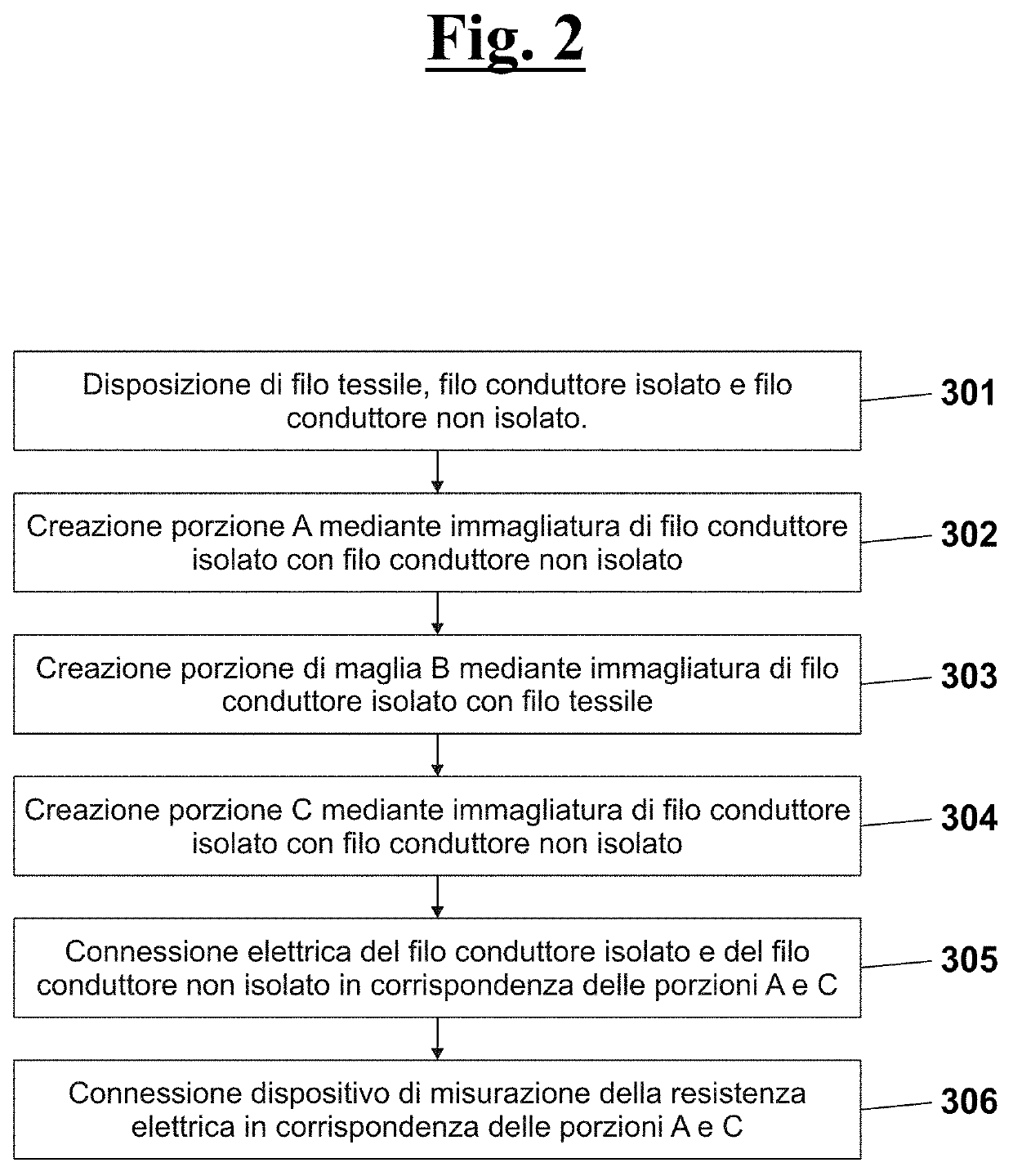
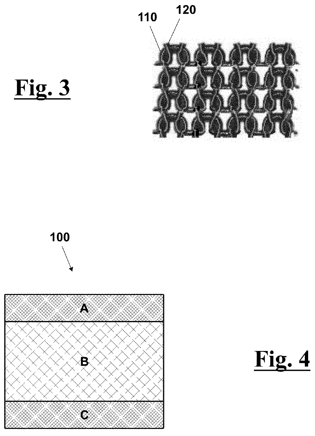
[0072]In FIG. 2 schematically shows the steps of the method necessary, according to the present invention, to generate the textile temperature sensor 100 of FIG. 4.

[0073]In particular, in a preliminary step [301] a textile wire 110, a conductive insulated wire 120 and a not conductive insulated wire are arranged on respective thread-guides of a linear knitting machine. The conductive insulated wire 120 can be, for example, an enameled copper wire, whereas the not conductive insulated wire can be, for example, a tinned copper wire. The textile wire 110 can be, for example, a polyester wire.

[0074]Then you proceed meshing the wires. With reference to FIGS. 2 and 4, following the generation of the portions from A to C, you have the following steps of meshing:[0075]portion A: meshing conductive insulated wire 120 and not conductive insulated wire [302];[0076]portion B: meshing conductive not insulated and textile wire 110 [303];[0077]portion C: meshing conductive insulated wire 120 and n...


PUM

PropertyMeasurementUnit
conductiveaaaaaaaaaa
electric resistance measuringaaaaaaaaaa
electric resistanceaaaaaaaaaa

Abstract

A method for manufacturing a textile temperature sensor, including arranging a linear knitting machine having a first thread-guide and a second thread-guide; arranging a conductive insulated wire on the first thread-guide; meshing the conductive insulated wire for making a mesh portion B having a nonconductive surface; arranging an electric resistance measuring device configured to measure a variation of electric resistance, the electric resistance being a function of the temperature; the measuring device phase of the electric resistance including a first electric cable and a second electric cable; electric connection of the first electric cable to the first end and of the second electric cable to the second end; and arranging a control unit arranged to receive from the device the variation of electric resistance in order to calculate excursions of the temperature at the lead wire.

Description

FIELD OF THE INVENTION[0001]The present invention relates to the field of thermistors, i.e. of the temperature sensors that exploit the variation of the resistivity of some materials at temperature variation.[0002]In particular, the invention relates to a textile thermistor.DESCRIPTION OF THE PRIOR ART[0003]A thermistor, or resistance thermometer, is a temperature sensor that exploits the variation of the resistivity of some materials at temperature variation.[0004]As well known, the resistance R generated by a conductive wire when current is passing is related to the resistivity of the material ρ according to the lawR=ρ*lA,where l e A are, respectively, length and section of the conductive wire.[0005]Furthermore, for metals exists a linear equation that links resistivity and temperature:ρ(T)=ρ0*[1+α(T−T0)][0006]Wherein:[0007]T is the temperature;[0008]ρ(T) is the resistivity of the material to the temperature T;[0009]ρ0 is the resistivity of the material to the temperature T0;[0010...

Claims


Application Information

Patent Timeline
21 Nov 2019
Publication
US20190353533A1
IPC
G01K7/18; H01B1/12; D04B1/14; D04B21/14; G01K1/14
CPC
G01K1/14; H01B1/124; G01K7/18; D10B2403/02431; D04B1/14; D04B21/14; A41D13/1281; A61B5/6804
Inventors
MARCHESI, RICCARDO