
Method for measuring an impedance of an electric cable, a coupler arrangement and uses thereof

a technology of impedance measurement and electric cable, which is applied in the direction of impedence measurement, resistance/reactance/impedence, instruments, etc., can solve the problems of cable insulation material degradation, cable insulation of electric cables will deteriorate, and cable insulation material may also be degraded locally. , to achieve the effect of cost-effective failure analysis

Active Publication Date: 2019-12-05
WIRESCAN
View PDF0 Cites 5 Cited by
  • Summary
  • Abstract
  • Description
  • Claims
  • Application Information

AI Technical Summary

Benefits of technology

The patent describes a method for monitoring the condition of an electric cable by measuring its electromagnetic nearfield using a capacitive sensor for the electric field and an inductive sensor for the magnetic field. The method can be used on both disconnected and live cables, and can provide valuable information without the need for a direct connection to the cable. The invention also opens up the use of the LRA method and system for analyzing the current and voltage noise on the cable under full power conditions. The technical effects of the patent include improved monitoring of electric cables and cost-efficient failure analysis of cables under full operating voltage and current.

Problems solved by technology

The cable insulation of electric cables will deteriorate over time.
The degradation rate of the cable insulation increases due to harsh environment conditions as high temperature, humidity and radiation.
The cable insulation material may also be degraded locally due to mechanical effects or local abnormal environment conditions.
Such global and local degradation of cable insulation and also power line breakage occur in all kinds of electric cables both for power and signal use.
Disconnecting the cable is not desirable as this involves additional work with disconnecting and connecting, and may include shutting down entire power systems.
These procedures are costly and time consuming.
In critical applications, such as nuclear power plants and power distribution lines, shutting down the system may also involve undesirable risks.
This also have the effect that such critical electric cables are not condition monitored as often as desirable.

Method used


Image

  • Method for measuring an impedance of an electric cable, a coupler arrangement and uses thereof
  • Method for measuring an impedance of an electric cable, a coupler arrangement and uses thereof
  • Method for measuring an impedance of an electric cable, a coupler arrangement and uses thereof

Examples


Embodiment Construction

[0039]The present invention will now be described with reference to the drawings.

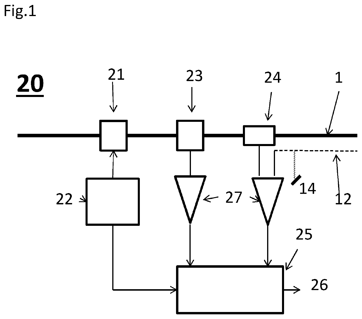
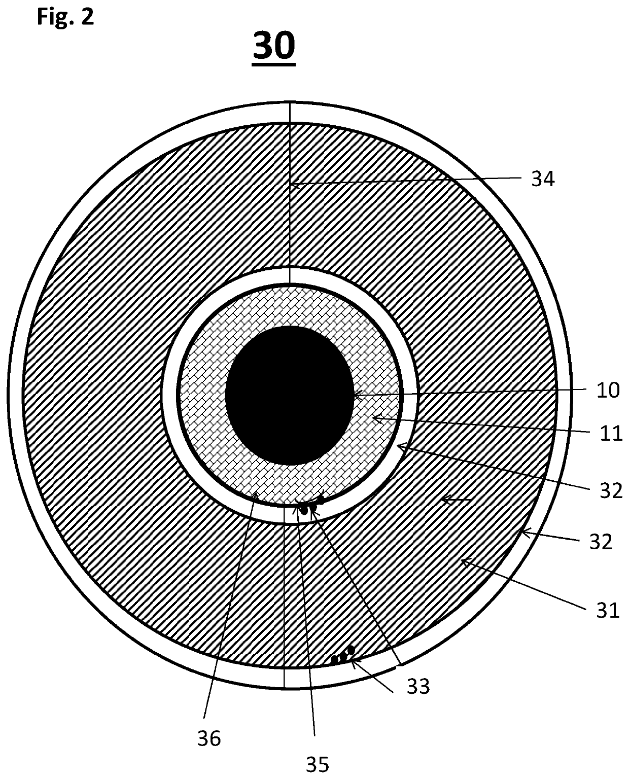
[0040]FIG. 1 illustrates a coupling arrangement 20 for electric cable monitoring connected to an electric cable 1 (power line or signal cable). The power line 1 under test in FIG. 1 has an insulating layer (not shown). The insulation may include a semi-conductive outer layer 36 (FIG. 2). A possible outer sheath and a cable screen 12 of the cable 1 are removed to expose the cable insulation 11 in the measurement area of the coupling arrangement 20. The measurement area is a freely chosen point on the cable. The cable screen 12 is connected to a common earth with the electronic monitoring system (22, 27, 25). The electric cable 1 may be a powered (live) or unpowered electric cable. The coupling arrangement in FIG. 1 comprises a signal coupler 21, a current sensor 23 and a cable voltage sensor 24. The signal coupler 21 may be an inductive coupler or a capacitive coupler for inducing a test signal in the el...


PUM


Abstract

The invention relates to a method for cable condition monitoring of an electric cable. The method comprises inducing a test current in the electric cable, measuring a resulting current in a measurement point of the electric cable by measuring a magnetic nearfield of the electric cable, measuring a resulting voltage in the measurement point of the electric cable by measuring an electric nearfield of the cable, calculating an impedance of the electric cable based on the resulting current and the resulting voltage by a line resonance analysis system, and analysing the impedance by the line resonance analysis system establishing a condition of the electric cable. A coupler arrangement providing a non-galvanic connection to the cable is also disclosed.

Description

INTRODUCTION[0001]The present invention concerns a method and a coupler arrangement for non-galvanic monitoring of an electric cable as well as uses of the invention. The measurements may be performed on disconnected as well as live cables.BACKGROUND[0002]Electric cables, both power and signal cables, are used in power generation, distribution and transmission, as cables in process industries, in aerospace industry, and onshore, offshore and subsea installations.[0003]The cable insulation of electric cables will deteriorate over time. The degradation rate of the cable insulation increases due to harsh environment conditions as high temperature, humidity and radiation. The cable insulation material may also be degraded locally due to mechanical effects or local abnormal environment conditions. Such global and local degradation of cable insulation and also power line breakage occur in all kinds of electric cables both for power and signal use.[0004]A number of cable fail detection tec...

Claims


Application Information

Patent Timeline
Patent Type & Authority Applications(United States)
IPC IPC(8): G01R31/02G01R27/16
CPCG01R27/16G01R31/021G01R15/142G01R31/58G01R15/183G01R15/16G01R15/20G01R1/18G01R31/1272G01R27/26
Inventor FALLET, TRULSKOLBERG, SIGBJØRN
Owner WIRESCAN
Learn More