Check patentability & draft patents in minutes with Patsnap Eureka AI!

Intramedullary fixation device

a technology of intramedullary fixation and bone wall, which is applied in the field of uncemented intramedullary fixation devices, can solve the problems of damage or even fracture of the bone wall, and the limited extent of nailing

Active Publication Date: 2019-12-19
UNIV POLITECNICA DE VALENCIA +2
View PDF0 Cites 0 Cited by
  • Summary
  • Abstract
  • Description
  • Claims
  • Application Information

AI Technical Summary

Benefits of technology

The invention solves the problem of high stress in certain areas of the bone by improving stress distribution and damping, and avoiding possible damage or remodeling of the bone. The solution is a rod made up of wedge bolts and expanders through which a central screw is inserted, which results in a controlled radial deformation and optimal stress distribution along the entire wall of the bone. This approach helps achieve a more homogeneous distribution of stress and reduced stress concentration in certain areas.

Problems solved by technology

These implant methods may cause damage or even fractures in the bone wall, thus there is a need of avoiding insertion of the rod in the bone with interference by hammering, or machining threads in the intramedullary canal.
The flanges or balls move outwardly by the action of the central conical elements, however, these elements do not have a geometry which restrains the maximum nailing, but said maximum nailing is limited exclusively by the screw distance between the two opposing central conical elements.
The system described in U.S. Pat. No. 4,453,539 does not guarantee that all the chamfer surface of the retractable flanges is in contact with the surface of the central conical element, which means that the piece usually acts as a cam with a significant point contact.

Method used


Image

  • Intramedullary fixation device
  • Intramedullary fixation device
  • Intramedullary fixation device

Examples


Embodiment Construction

[0028]The following is a brief description of an embodiment of the invention as an illustrative and non- limiting example thereof.

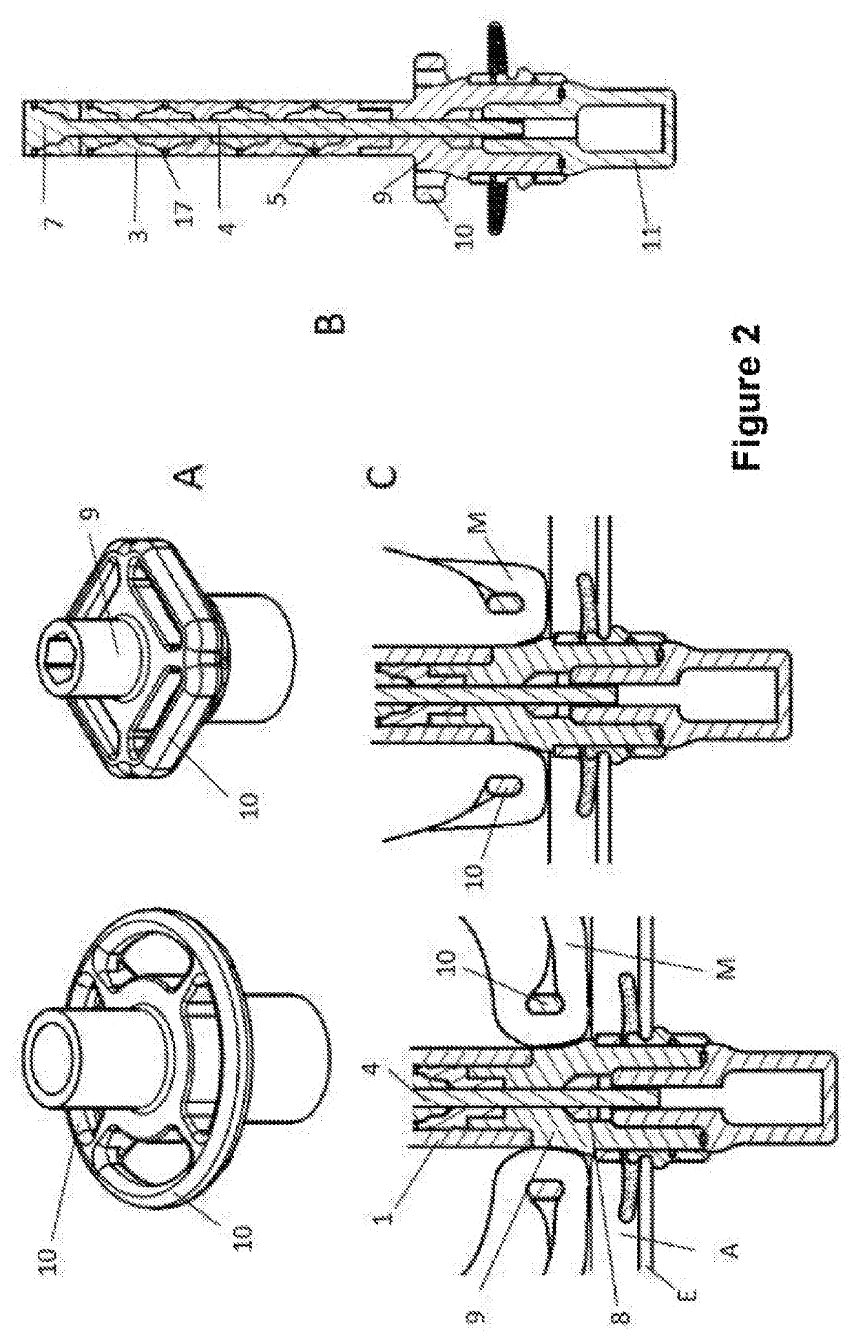
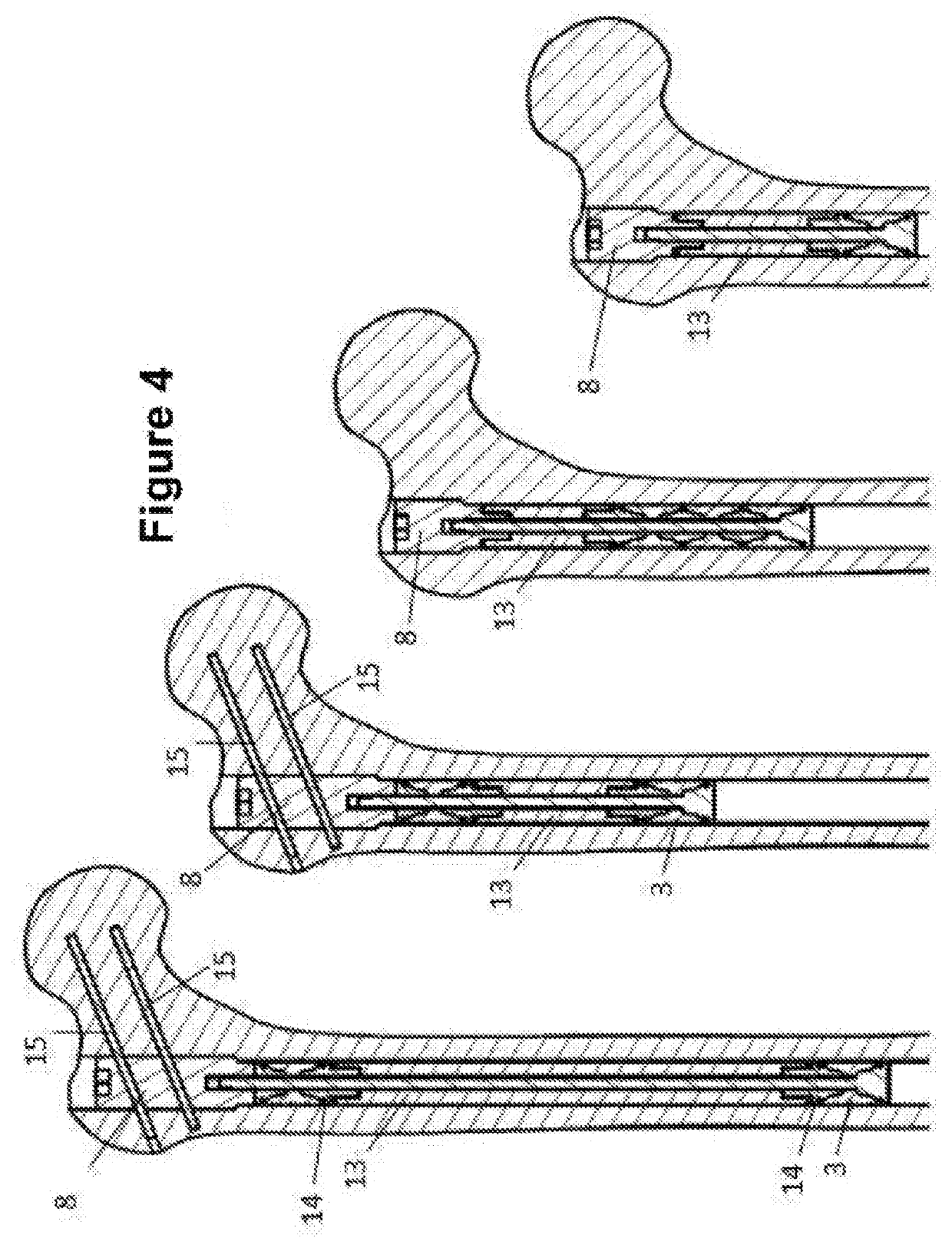
[0029]The invention refers to a device for fixation thereof to the intramedullary wall of a bone (1), consisting of a rod (2) and usually an additional component that will depend on the objective intended.

[0030]The rod (2) is formed by a number of expanders (3) (which can be decoupled from the central bar), made by biocompatible, polymer or metal modules or cylinders. For example, the expanders (3) will be coated with a titanium alloy, hydroxyapatite or any other biocompatible coating material which promotes subsequent osseointegration with the bone (1). The modules will be arranged in a central screw (4) passing through the expanders (3) via an inner hole.

[0031]Between each pair of consecutive expanders (3) corresponding bolts (5) are arranged, being also mounted in the central screw (4) (although they can be decoupled therefrom), the faces of which bein...


PUM


Abstract

Intramedullary fixation device, having an intramedullary rod (2) which is provided for insertion thereof into a bone (1) and consists of a central screw (4) having a first free end comprising a stopper (7) and a second free end with a pre-tensioning nut (8), an alternating series of expanders (3) and bolts (5) being arranged in between, the bolt surfaces in contact with the expanders (3) having a wedge shape. The bolts (5) or expanders (3) may have no, or one or more variations in the dimensions of the different geometric parameters, in accordance with the adjacent expanders, along the length of the implant, and the central screw (4) may have a variable cross section. The device may have different additional components, such as an osteotomic base (9) for fixation of the musculature. The device promotes maximum nailing limited between these elements and produces a controlled peripheral radial deformation.

Description

TECHNICAL FIELD[0001]The present invention relates to an uncemented intramedullary fixation device, which is inserted in the medullary canal of long bones and allows arranging elements of internal or external prosthesis or assisting in the reconstruction of fractures, among other uses.STATE OF THE ART[0002]There are several ways for fixation of elements by means of press fitted intramedullary rods. The most common is that of inserting a rigid rod being percussed into the bone. In exo-prosthetization applications, the OPRA system performs machining of a thread in the bone wall so as to fix the implant. These implant methods may cause damage or even fractures in the bone wall, thus there is a need of avoiding insertion of the rod in the bone with interference by hammering, or machining threads in the intramedullary canal.[0003]WO 02058575 describes expansion modules (10) formed by six deformable longitudinal portions (12), the ends of which having a blocking mechanism in the manner of...

Claims


Application Information

Patent Timeline
IPC IPC(8): A61B17/72A61F2/36A61F2/30
CPCA61F2/30749A61B17/7275A61F2002/7887A61F2/3601A61F2002/30777A61F2/78A61B17/744A61F2/36A61F2/3609A61F2/3662A61F2002/3652
Inventor EXPOSITO OLLERO, JOSEALBELDA VITORIA, JOSEHOYOS FUENTES, JUAN VICTORVALLES LLUCH, ANASILVESTRE MUNOZ, ANTONIO
Owner UNIV POLITECNICA DE VALENCIA
Features
  • R&D
  • Intellectual Property
  • Life Sciences
  • Materials
  • Tech Scout
  • Unparalleled Data Quality
  • Higher Quality Content
  • 60% Fewer Hallucinations
Learn More