Supercharge Your Innovation With Domain-Expert AI Agents!

Oscillation control system and oscillation control method

a control system and oscillation control technology, applied in the field of oscillation control system and oscillation control method, can solve the problems of inefficiency of operations, additional costs in edition or equipment, and inability to carry out control design of systems with accelerometers using related feedback methods in state space system form, so as to avoid complicated operations and simplify the system

Active Publication Date: 2020-01-02
I-SHOU UNIVERSITY
View PDF5 Cites 0 Cited by
  • Summary
  • Abstract
  • Description
  • Claims
  • Application Information

AI Technical Summary

Benefits of technology

The present invention provides an oscillation control system and method that uses a reciprocal state space system, which simplifies the system and reduces costs. The system can directly introduce the measured acceleration value for editing the state derivative feedback without using extra devices for integral operations, resulting in faster and more accurate control. The output vector operates the actuator by the input vector through the feedback gain, which can control the deformation state of the actuator. The feedback gain is adjusted to stabilize the closed-loop procedure, ensuring fast stability and accurate control. In summary, the system provides a fast and reliable solution for controlling oscillations.

Problems solved by technology

However, the operational voltage value is not completely linearly related to the deformation displacement due to the hysteresis of piezoelectric materials, such that the same voltage value renders different displacements in the step-up procedure and the step-down procedure.
However, the acceleration can only be expressed by the state derivative rather than the state vector, the popular state related feedback methods in state space system form are not suitable to carry out control designs for systems with accelerometers as sensors.
Both the above two methods require additional costs in edition or equipment, and the operations are not efficient.

Method used


Image

  • Oscillation control system and oscillation control method
  • Oscillation control system and oscillation control method

Examples


Embodiment Construction

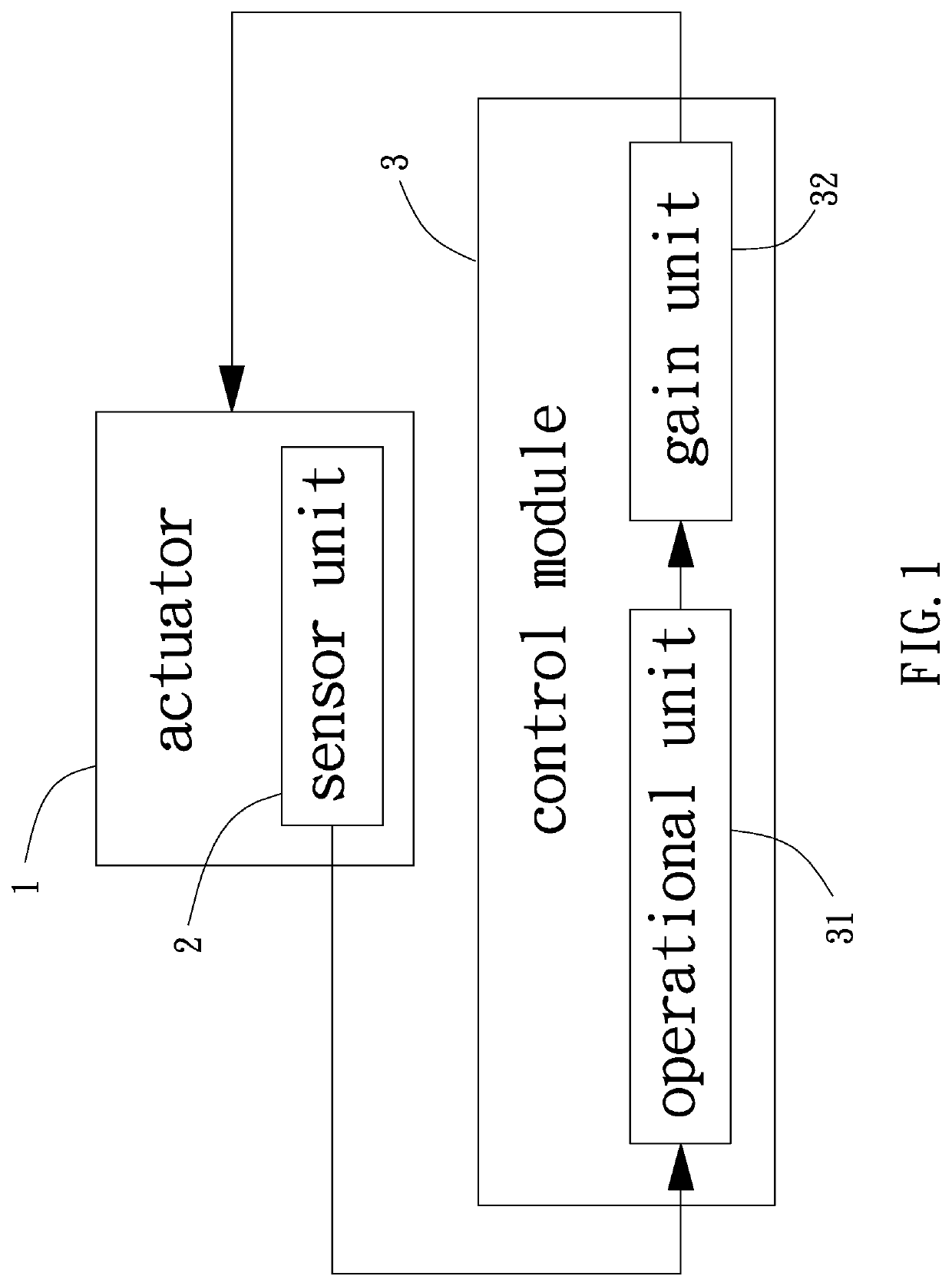
[0020]With reference to FIG. 1, an oscillation control system of an embodiment according to the present invention includes an actuator 1, a sensor unit 2, and a control module 3. The sensor unit 2 is located on the actuator 1. The control module 3 is coupled to the actuator 1 and the sensor unit 2.

[0021]The actuator 1 includes at least one piezoelectric material coupled with an electrode. The piezoelectric material can be a copolymer of polyvinylidene difluoride (PVDF). When the electrode applies an electric field to the piezoelectric material, the piezoelectric material elongates in the direction of the electric field and causes curving and deformation of the actuator 1.

[0022]The sensor unit 2 can be an acceleration sensor and is preferably located on a curved face of the actuator 1. The sensor unit 2 is configured to detect an acceleration value of the deformation of the actuator 1.

[0023]The control module 3 includes an operational unit 31 which can be a microprocessor. The operat...


PUM


Abstract

An oscillation control system includes an actuator, a sensor unit, and a control module. An actuator includes at least one piezoelectric material coupled with an electrode. The sensor unit is located on the actuator and is configured to detect an acceleration value of deformation of the actuator. A control module includes an operational unit and a gain unit. The operational unit generates an operational result according to the acceleration value and conditions of the actuator. The gain unit is coupled to the operational unit and the electrode and is configured to convert the operational result into a control signal which adjusts the actuator. An oscillation control method includes using a reciprocal state space system to proceed with closed-loop control of a state derivative feedback. The reciprocal state space system is represented by a plurality of equations.

Description

CROSS REFERENCE TO RELATED APPLICATION[0001]The application claims the benefit of Taiwan application serial No. 107122838, filed on Jul. 2, 2018, and the entire contents of which are incorporated herein by reference.BACKGROUND OF THE INVENTION1. Field of the Invention[0002]The present invention relates to an oscillation control system and an oscillation control method and, more particularly, to an oscillation control system and an oscillation control method providing a quick reaction speed and accurate displacement control.2. Description of the Related Art[0003]The amplitude displacement smaller than 1 mm is required in the fields of optics, precision machinery, and micromotors. Moreover, a technology controlling the displacement precision to be in the order of 0.01 mm can use the piezoelectric effect which is a conversion between the electrical energy and the mechanical energy. A voltage is applied to a piezoelectric material which resists the change and, thus, generates mechanical...

Claims


Application Information

Patent Timeline
IPC IPC(8): G01P15/09H01L41/08H01L41/04H03B5/32
CPCH01L41/0825H01L41/1132H01L41/042H03B5/32G01P15/09G05B13/024H03B2200/0066H03L7/00H10N30/802H10N30/101H10N30/302
Inventor TSENG, YUAN-WEIWU, RONG-CHINGTSAI, CHIA-CHUAN
Owner I-SHOU UNIVERSITY
Features
  • R&D
  • Intellectual Property
  • Life Sciences
  • Materials
  • Tech Scout
  • Unparalleled Data Quality
  • Higher Quality Content
  • 60% Fewer Hallucinations
Learn More