Pressurized inerting system

a technology of compressed air and inerting gas, which is applied in the direction of transportation and packaging, separation processes, dental surgery, etc., can solve the problems of reducing the power of the available engine, and reducing the payload of the aircra

Inactive Publication Date: 2020-01-09
HAMILTON SUNDSTRAND CORP
View PDF3 Cites 11 Cited by
  • Summary
  • Abstract
  • Description
  • Claims
  • Application Information

AI Technical Summary

Problems solved by technology

Bleed air from an aircraft engine or from an onboard auxiliary power unit can provide a source of compressed air; however, this can reduce available engine power and also must compete with other onboard demands for compressed air, such as the onboard air environmental conditioning system and anti-ice systems.
Moreover, certain flight conditions such as during aircraft descent can lead to an increased demand for NEA at precisely the time when engines could be throttled back for fuel savings so that maintaining sufficient compressed air pressure for meeting the pneumatic demands may come at a significant fuel burn cost.
A separate compressor or compressors can be used to provide pressurized air to the membrane gas separator, but this undesirably increases aircraft payload, and also represents another onboard device with moving parts that is subject to maintenance issues or device failure.

Method used


Image

  • Pressurized inerting system
  • Pressurized inerting system
  • Pressurized inerting system

Examples


Embodiment Construction

[0026]A detailed description of one or more embodiments of the disclosed apparatus and method are presented herein by way of exemplification and not limitation with reference to the Figures

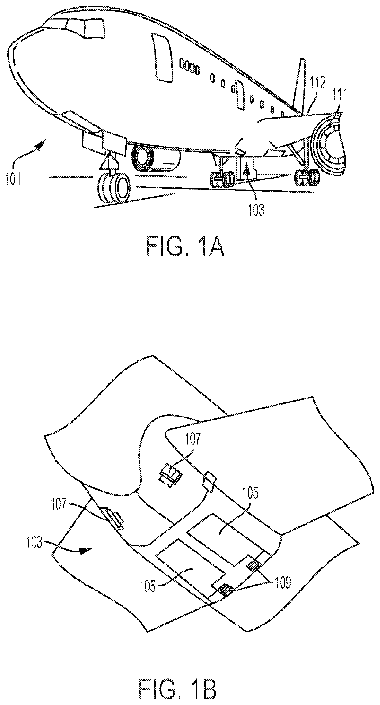
[0027]As shown in FIGS. 1A-1B, an aircraft includes an aircraft body 101, which can include one or more bays 103 beneath a center wing box. The bay 103 can contain and / or support one or more components of the aircraft 101. For example, in some configurations, the aircraft can include environmental control systems and / or fuel inerting systems within the bay 103. As shown in FIG. 1B, the bay 103 includes bay doors 105 that enable installation and access to one or more components (e.g., environmental control systems, fuel inerting systems, etc.). During operation of environmental control systems and / or fuel inerting systems of the aircraft, air that is external to the aircraft can flow into one or more ram air inlets 107. The outside air may then be directed to various system components (e.g., enviro...


PUM


Abstract

A system for providing inerting gas to a protected space is disclosed. The system includes an electrochemical cell that produces inerting gas on a cathode fluid flow path, and delivers it to an inerting gas flow path is disposed in operative fluid communication with the cathode fluid flow path outlet and the protected space. The inerting gas flow path includes a condenser that receives inerting gas from the cathode fluid flow path outlet, and also includes a pressure control device configured along with the pressurized gas source to provide a pressure at the condenser greater than ambient pressure.

Description

BACKGROUND[0001]The subject matter disclosed herein generally relates to systems for providing inerting gas, and more particularly to inerting systems for aircraft fuel tanks.[0002]It is recognized that fuel vapors within fuel tanks become combustible or explosive in the presence of oxygen. An inerting system decreases the probability of combustion or explosion of flammable materials in a fuel tank by maintaining a chemically non-reactive or inerting gas, such as nitrogen-enriched air, in the fuel tank vapor space, also known as ullage. Three elements are required to initiate combustion or an explosion: an ignition source (e.g., heat), fuel, and oxygen. The oxidation of fuel may be prevented by reducing any one of these three elements. If the presence of an ignition source cannot be prevented within a fuel tank, then the tank may be made inert by: 1) reducing the oxygen concentration, 2) reducing the fuel concentration of the ullage to below the lower explosive limit (LEL), or 3) in...

Claims


Application Information

Patent Timeline
Patent Type & Authority Applications(United States)
IPC IPC(8): A62C2/00B01D53/32B01D53/26B64D45/00B64D37/32
CPCB01D53/265A62C2/00B64D37/32B64D2045/009B64D45/00B01D53/326A62C3/08A62C99/0018Y02T50/40
Inventor RHEAUME, JONATHAN
Owner HAMILTON SUNDSTRAND CORP
Why Eureka
Try Eureka