Burst-mode chirped pulse amplification method

Active Publication Date: 2020-01-16
LAWRENCE LIVERMORE NAT SECURITY LLC
View PDF0 Cites 0 Cited by
  • Summary
  • Abstract
  • Description
  • Claims
  • Application Information

AI Technical Summary

Benefits of technology

The present technology provides a method for increasing the yield of hot electrons produced by short-pulse laser interactions compared to conventional methods. These hot electrons can be used to create useful secondary or tertiary radiation for various applications such as flash radiography or medical imaging. The method involves amplifying short pulses using a technique called burst-mode CPA, which increases the maximum energy the final optics can handle without damage by introducing energy in a burst of short pulses. The method also addresses the non-linear effects and optical damage limits of traditional amplification systems by injecting the pulses into the amplifier at points separated by distances sufficient to avoid laser plasma interactions between pulses. Finally, the method reduces the laser plasma interaction between strike points on the target by using recessed or isolated targets.

Problems solved by technology

This process (known as the Kerr effect) seeds instabilities in the beam resulting in distortion and ultimately, in a collapse into localized destructive filaments.
These limits on energy are often far below (e.g., 10 times below) the available stored energy in the stretched pulse amplifier making CPA an inefficient process.
This is clearly highly inefficient in terms of system cost and size.
However, because of non-linear effects in the main amplifier accumulation of B-integral), and the optical damage limits of the final compression and focusing optics, CPA is an inefficient process that leaves gain in the main amplification stage that cannot be extracted to produce short-pulses without incurring either deleterious effects to the laser pulse or outright damage of the amplifier media, compressor optics or the final optics which include focusing, optics and transport optics, The present technology, referred to sometimes herein as Burst-Mode CPA (BM-CPA), provides a means to extract this gain through the amplification of a burst of short pulses.

Method used


Image

  • Burst-mode chirped pulse amplification method
  • Burst-mode chirped pulse amplification method
  • Burst-mode chirped pulse amplification method

Examples


example 1

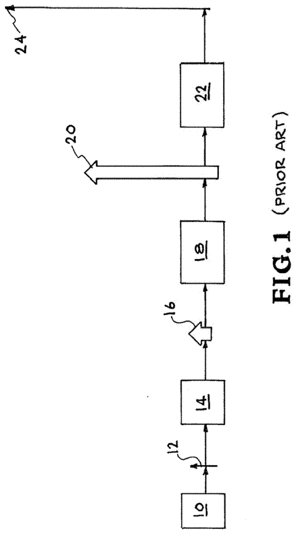
[0029 of FIG. 7A in general is a block diagram showing a single seed pulse, a burst generator, a stretcher, an amplifier (pre and final) and a compressor. All systems of examples 1-4 (FIGS. 7A-7D) are followed by focusing optics for directing the pulses onto the target (not shown) such as target 60 of FIGS. 4A and 4B. In this configuration, a laser front end 100 produces a low energy short pulse “seed”112. Seed pulse 112 passes through burst generator 80 to produce a series of short pulses which are stretched in time by stretcher 114 to produce a series of stretched pulses 116. Amplifier 118, which may include a preamplifier 118′ and a final amplifier 118″, amplifies the series of stretched pulses 116 to produce a series of stretched pulses 120. Compressor 122 compresses series of amplified pulses 120 in time to produce a series of compressed pulses 124.

example 2

[0030 of FIG. 7B in general is a block diagram showing a single seed pulse, a stretcher, a burst generator, an amplifier (pre and final) and a compressor. In this configuration, a laser front end 100 produces a low energy short pulse “seed”112. Seed 112 passes through pulse stretcher 114 to produce a stretched pulse 116 which then passes through burst generator 80 to produce a series of stretched pulses which are then directed through amplifier 118. Amplifier 118, which may include a preamplifier 118′ and a final amplifier 118″, amplifies pulses 116 to produce a series of amplified pulses 120. Compressor 122 compresses the pulses in time. Thus, the output pulses from compressor 122 are a series of compressed pulses 124.

example 3

[0031 of FIG. 7C in general is a block diagram showing a single seed pulse, a stretcher, a pre-amplifier, a burst generator, a final amplifier and a compressor. In this configuration, a laser front end 100 produces a low energy short pulse “seed”112. Seed 112 passes through pulse stretcher 114 to produce a stretched pulse 116 which, as shown in the insert, then passes through preamplifier 118′ and then burst generator 80 followed by final amplifier 118′ which amplifies the series of pre-amplified pulses 116 to produce a high energy stretched series of pulses 120 that are directed into compressor 122 which compresses the series of amplified pulses to produce a series of high energy output pulses 124.


PUM


Abstract

A method for increasing the MeV hot electron yield and secondary radiation produced by short-pulse laser-target interactions with an appropriately high or low atomic number (Z) target. Secondary radiation, such as MeV x-rays, gamma-rays, protons, ions, neutrons, positrons and electromagnetic radiation in the microwave to sub-mm region, can be used, e.g., for the flash radiography of dense objects.

Description

CROSS-REFERENCE TO RELATED APPLICATIONS[0001]This application claims the benefit of U.S. Provisional Patent Application No. 62 / 697,571 titled “Burst-Mode Chirped Pulse Amplification for Increased Laser-Driven MeV Hot Electron and Secondary Photon and Particle Generation,” filed Jul. 13, 2018, incorporated herein by reference.STATEMENT AS TO RIGHTS TO INVENTIONS MADE UNDER FEDERALLY SPONSORED RESEARCH OR DEVELOPMENT[0002]The United States Government has rights in this invention pursuant to Contract No. De-AC52-07NA27344 between the United States Department of Energy and Lawrence Livermore National Security, LLC, for the operation of Lawrence Livermore National Laboratory.BACKGROUNDField[0003]The present technology relates to chirped pulse amplification systems, and more specifically, relates to technology for increasing the MeV hot electron yield produced by short-pulse laser-target interactions over that produced by high-energy chirped pulse amplification systems.Description of Rela...

Claims


Application Information

Patent Timeline
IPC IPC(8): G21K5/02H01S3/00H01S3/23
CPCG21K5/02H01S3/0057H01S3/2316H05G2/00H05H15/00H05H6/00H01S3/2308H01J35/065H01S3/06758H01S3/1301H01S5/0057H01S3/10023H01S5/5018H01S3/10007H01S5/5027
Inventor BUDE, JEFFREY D.ALESSI, DAVID A.AUFDERHEIDE, MAURICE B.HEEBNER, JOHN E.KEMP, ANDREAS J.LANDEN, OTTO L.MACKINNON, ANDREW J.NEGRES, RALUCA A.SIDERS, CRAIG W.WILKS, SCOTT C.WILLIAMS, WADE H,YANG, STEVEN T.SPINKA, THOMAS M.
Owner LAWRENCE LIVERMORE NAT SECURITY LLC
Why Eureka
Try Eureka