Supersonic aircraft turbofan

a turbofan and aircraft technology, applied in the direction of machines/engines, mechanical equipment, transportation and packaging, etc., can solve the problems of high take off speed, low maximum lift, and add weight and engine architecture complexity, so as to reduce the area of the variable area throat, reduce the noise of the jet, and the engine thrust is high.

Active Publication Date: 2020-01-23
ROLLS ROYCE PLC
View PDF0 Cites 1 Cited by
  • Summary
  • Abstract
  • Description
  • Claims
  • Application Information

AI Technical Summary

Benefits of technology

[0017]wherein, to achieve a high level of engine thrust during the take-off operation, the controller performs or is configured to perform the take-off operation with a reduced area of the v

Problems solved by technology

However, a variable geometry intake requires a complex intake actuation system which adds weight and engine architecture complexity.
This is because supersonic aircraft have a low wing area and a correspondingly low maximum l

Method used


Image

  • Supersonic aircraft turbofan
  • Supersonic aircraft turbofan
  • Supersonic aircraft turbofan

Examples


Embodiment Construction

1. Engine

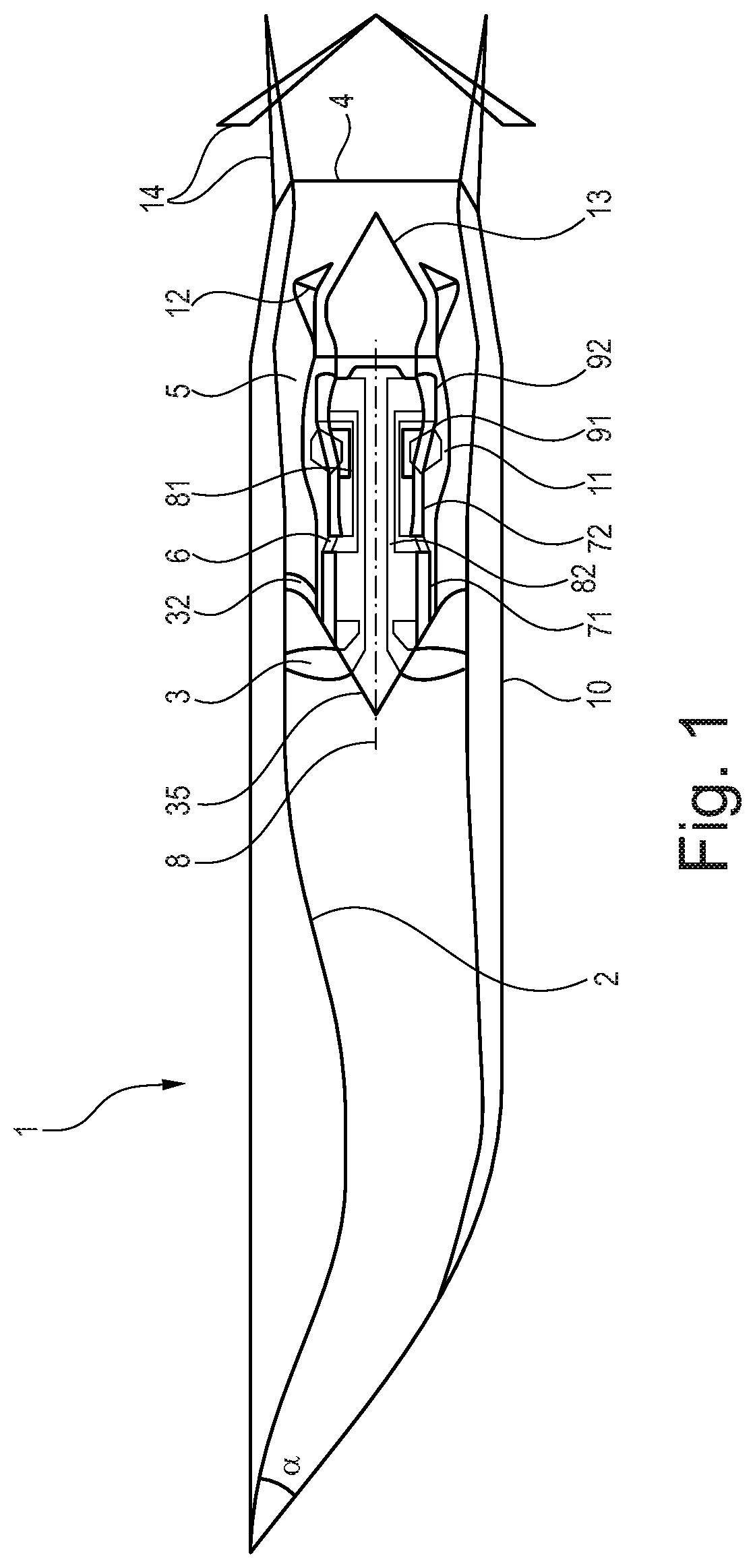
[0048]FIG. 1 shows a longitudinal cross-section through a turbofan engine 1 for a civil supersonic aircraft. The turbofan engine 1 comprises an engine intake 2, a single stage fan 3 (although in other embodiments a multi-stage fan can be used), a primary flow channel 6 that leads through a engine core, a secondary flow channel 5 that leads past the engine core, a multi-lobed mixer 12, and a thrust nozzle 4 into which a thrust reverser 14 (shown in both stowed and deployed configurations) can be integrated.

[0049]The turbofan engine 1 has a machine axis or engine centre line 8. The machine axis 8 defines an axial direction of the turbofan engine. A radial direction of the turbofan engine extends perpendicularly to the axial direction.

[0050]The engine core comprises in a per se known manner a compressor 71, 72, a combustion chamber 11 and a turbine 91, 92. In the shown exemplary embodiment, the compressor comprises a booster compressor 71 and a high-pressure compressor 72. The...


PUM


Abstract

A turbofan engine has an engine core including in flow series a compressor, a combustor and a turbine. The engine further has a fan located upstream of the engine core, has a supersonic intake for slowing down incoming air to subsonic velocities at an inlet to the fan formed by the intake, has a bypass duct surrounding the engine core, wherein the fan generates a core airflow to the engine core and a bypass airflow through the bypass duct, and has a mixer for mixing an exhaust gas flow exiting the engine core and bypass airflow exiting bypass duct. The engine further has a thrust nozzle rearwards of the mixer for discharging mixed flows, the thrust nozzle having a variable area throat. The engine further has a controller controlling the thrust produced by the engine over a range of flight operations including on-the-ground subsonic take-off and subsequent off-the-ground subsonic climb.

Description

CROSS-REFERENCE TO RELATED APPLICATIONS[0001]This specification is based upon and claims the benefit of priority from United Kingdom patent application number GB 1811852.1 filed on Jul. 20, 2018, the entire contents of which are incorporated herein by reference.BACKGROUNDField of the Disclosure[0002]The present disclosure relates to a turbofan for a supersonic aircraft.Description of the Related Art[0003]There is a growing interest in the development of supersonic aircrafts for civil use. In particular, gas turbine engine systems that effectively provide thrust in subsonic, transonic and supersonic flight regimes, with reduced noise output during certain operations, are of interest.[0004]Such engines have special adaptations relative to more conventional engines used purely for subsonic flight. For example, gas turbine engines are not designed to operate with an airflow velocity that is greater than Ma 1.0 (Ma=Mach number) for the airflow entering the engine compression section. The...

Claims


Application Information

Patent Timeline
IPC IPC(8): F02C9/20B64D33/04B64D31/06B64D33/02F02K3/06F02C9/54
CPCF05D2270/095F05D2220/80B64D29/04B64D33/02F05D2270/051F02K3/06B64D2033/0286F05D2220/323F05D2260/96F05D2270/71B64D33/04F02C9/20F02C9/54B64D31/06F02K1/06F02K1/17F02K3/075
Inventor STIEGER, RORY DHICKEY, CONOR
Owner ROLLS ROYCE PLC
Why Eureka
Try Eureka