Gas laser apparatus and magnetic bearing control method

a laser and magnetic bearing technology, applied in the direction of magnetically actuated clutches, mechanical energy handling, mechanical equipment, etc., can solve problems such as reducing resolution

Active Publication Date: 2020-01-23
GIGAPHOTON
View PDF0 Cites 5 Cited by
  • Summary
  • Abstract
  • Description
  • Claims
  • Application Information

AI Technical Summary

Benefits of technology

[0020]A magnetic bearing control method according to an aspect of the present disclosure used in a gas laser apparatus including a laser chamber in which a laser gas is encapsulated, a pair of discharge electrodes arranged in the laser chamber to oppose each other, and a fan configured to supply the laser gas between the discharge electrodes, the magnetic bearing control method being used for controlling a

Problems solved by technology

Thus, chromatic aberration of a laser beam (ultraviolet light) reduced projected on

Method used


Image

  • Gas laser apparatus and magnetic bearing control method
  • Gas laser apparatus and magnetic bearing control method
  • Gas laser apparatus and magnetic bearing control method

Examples


first embodiment

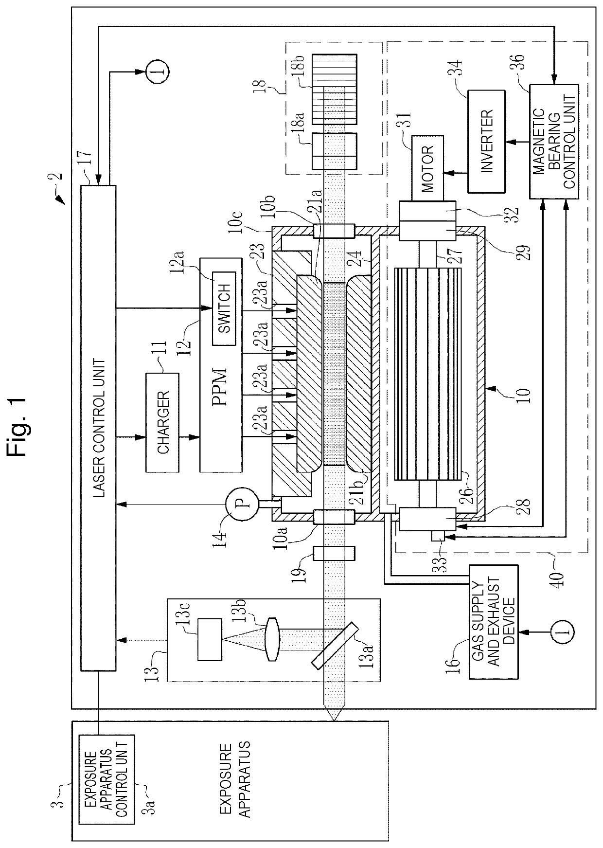
3. Gas laser apparatus of first embodiment

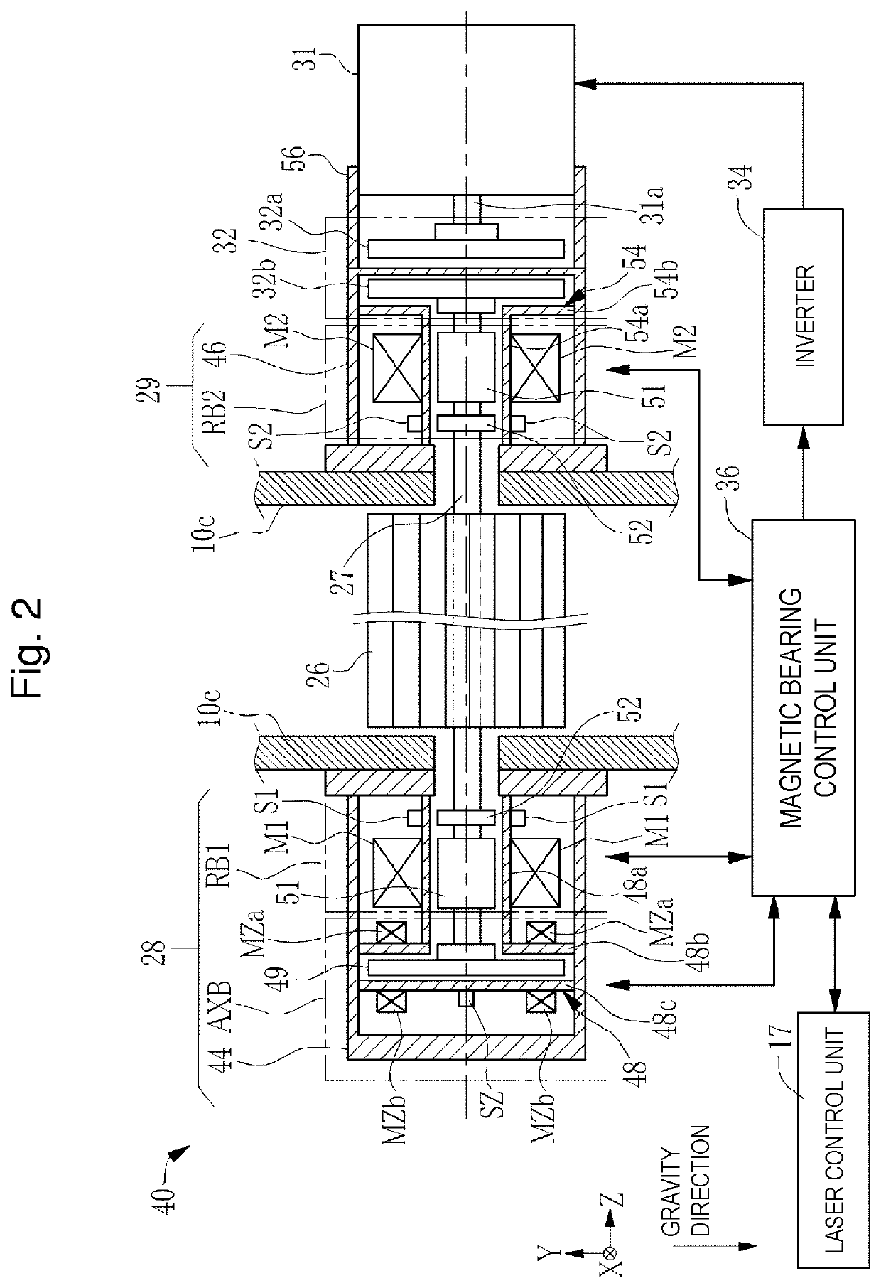
[0117]3.1 Configuration of magnetic bearing system of fan

[0118]3.1.1 Magnetic flux density sensor

[0119]3.1.2 Configuration of magnetic bearing control unit

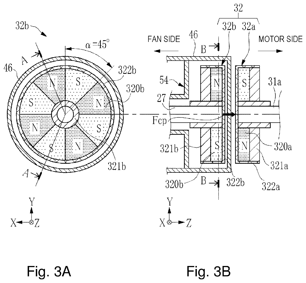
[0120]3.1.3 CP attractive force measuring method

[0121]3.2 Operation of magnetic bearing system

[0122]3.2.1 Control flow of radial electromagnet control unit

[0123]3.2.2 Processing of CP attractive force measuring unit

[0124]3.2.3 Control flow of axial electromagnet control unit CZA

[0125]3.3 Effect

[0126]3.3.1 First effect

[0127]3.3.2 Second effect

[0128]3.3.3 Third effect

[0129]3.4 Abnormality determination of CP attractive force

[0130]3.5 Variant of magnetic coupling

[0131]3.6 PID control

[0132]3.7 Others[0133]4. Gas laser apparatus of second embodiment

[0134]4.1 Configuration of magnetic bearing system of fan

[0135]4.1.1 Magnetic flux density change sensor

[0136]4.1.2 CP attractive force measuring method

[0137]4.2 Operation of magnetic bearing system

[0138]4.2.1 Processing of CP attractive force measur...


PUM


Abstract

A gas laser apparatus includes: a magnetic bearing including an electromagnet capable of controlling a magnetic force, and configured to rotatably support a rotary shaft of a fan in a magnetically levitated state by the magnetic force, the fan being configured to supply a laser gas; an electromagnet control unit configured to control the magnetic force of the electromagnet based on displacement of a levitated position of the rotary shaft and adjust the levitated position; a motor configured to generate torque for rotating the fan; a magnetic coupling configured to couple the rotary shaft and a drive shaft of a motor with a magnetic attractive force and transmit the torque of the motor to the rotary shaft; an attractive force estimating sensor configured to detect a parameter that enables an attractive force of the magnetic coupling to be estimated; an attractive force measuring unit configured to measure the attractive force of the magnetic coupling based on the detected parameter; and a correction unit configured to correct the magnetic force of the electromagnet according to a variation in the attractive force measured by the attractive force measuring unit.

Description

CROSS-REFERENCE TO RELATED APPLICATIONS[0001]The present application is a continuation application of International Application No. PCT / JP2017 / 015630 filed on Apr. 18, 2017. The content of the application is incorporated herein by reference in its entirety.BACKGROUND1. Technical Field[0002]The present disclosure relates to a gas laser apparatus and a magnetic bearing control method.2. Related Art[0003]Improvements in resolution of semiconductor exposure apparatuses (hereinafter simply referred to as “exposure apparatuses”) have been desired due to miniaturization and high integration of semiconductor integrated circuits. For this purpose, exposure light sources that emit light with shorter wavelengths have been developed. As the exposure light source, a gas laser apparatus is used instead of a conventional mercury lamp. As the gas laser apparatus for exposure, a KrF excimer laser apparatus that outputs ultraviolet light with a wavelength of 248 nm and an ArF excimer laser apparatus ...

Claims


Application Information

Patent Timeline
IPC IPC(8): F16C32/04H02K7/09H02K49/10H01S3/036F16D27/00F16D27/14
CPCH02K7/09H01S3/036F16D27/14H01S3/038F16D27/004H02K49/108F16C32/0476F16C32/0489F16C2380/26F16D27/06H01S3/225H02K7/003
Inventor MIKI, MASAHARUWAKABAYASHI, OSAMU
Owner GIGAPHOTON
Why Eureka
Try Eureka