Method for producing an electrode stack for a battery cell, battery cell

a battery cell and electrode stack technology, applied in the direction of wound/folded electrode electrodes, cell components, batteries, etc., can solve the problems of reducing the capacity of the battery cell, metallized lithium is no longer available for charge transport, etc., and achieves the effect of reducing process time, avoiding or at least avoiding metallized lithium, and reducing the cost of production

Active Publication Date: 2020-01-23
ROBERT BOSCH GMBH
View PDF4 Cites 2 Cited by
  • Summary
  • Abstract
  • Description
  • Claims
  • Application Information

AI Technical Summary

Benefits of technology

The invention provides a method for making a battery electrode stack by using composite segments, which reduces the likelihood of metallization and increases the efficiency of the process. The method also reduces the time and cost associated with individual electrode and separator segment stacking. The use of grooves in the composite segments helps to remove active material from the current collector, which further reduces processing time and costs. The technical effects of this invention include improved safety and efficiency of battery production.

Problems solved by technology

Metallized lithium is then no longer available for the charge transport, and the capacity of the battery cell therefore decreases.

Method used


Image

  • Method for producing an electrode stack for a battery cell, battery cell
  • Method for producing an electrode stack for a battery cell, battery cell
  • Method for producing an electrode stack for a battery cell, battery cell

Examples


first embodiment

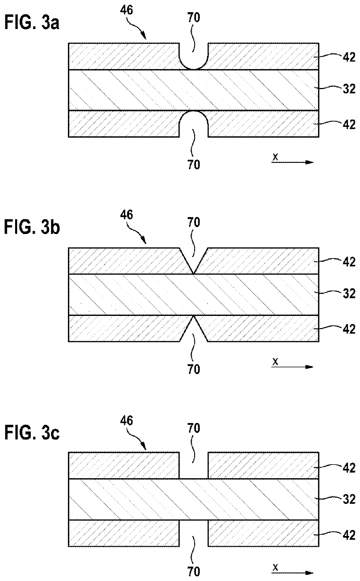
[0049]FIG. 3a shows a schematic sectional representation of the cathode element 46 along the section line A-A in FIG. 2 according to a The grooves 70 in this case have an approximately U-shaped cross section. The outer walls of the grooves 70 initially extend parallel to one another in a region away from the cathodic current collector 32, and merge into a semicircular rounding when approaching the cathodic current collector 32.

second embodiment

[0050]FIG. 3b shows a schematic sectional representation of the cathode element 46 along the section line A-A in FIG. 2 according to a The grooves 70 in this case have an at least approximately triangular cross section. The outer walls of the grooves 70 are spaced relatively wide apart from one another in a region away from the cathodic current collector 32, and extend at an angle to one another and converge when approaching the cathodic current collector 32.

third embodiment

[0051]FIG. 3c shows a schematic sectional representation of the cathode element 46 along the section line A-A in FIG. 2 according to a The grooves 70 in this case have an at least approximately rectangular cross section. The outer walls of the grooves 70 are spaced apart from one another in a region away from the cathodic current collector 32, and extend parallel to one another, and perpendicularly to the cathodic current collector 32, towards the cathodic current collector 32.

[0052]FIG. 4 shows a schematic sectional representation of a composite element 50, which comprises a cathode element 46 according to the first embodiment, as shown by FIG. 3a. The composite element 50 furthermore comprises an anode element 45, as well as a first separator element 16 and a second separator element 16.

[0053]The cathode element 46 is in this case applied onto the first separator element 16 and connected to the first separator element 16. The anode element 45 is applied on a side of the first sep...


PUM


Abstract

The invention relates to a method for producing an electrode stack for a battery cell, comprising the following steps: providing a strip-shaped anode element (45) comprising an anodic current discharger (31) to which an anodic active material (41) is applied; providing a strip-shaped cathode element (46) comprising a cathodic current discharger (32) to which a cathodic active material (42) is applied; providing at least one strip-shaped separator element (16); introducing grooves (70) into the cathodic active material (42) around segmentation lines (S); generating a strip-shaped composite element (50) by applying the cathode element (46) onto the anode element (45), with the interposition of the at least one separator element (16); cutting the composite element (50) into plate-shaped composite segments at the segmentation lines (S); and stacking the composite segments. The invention also relates to a battery cell comprising at least one electrode stack which is produced according to the method according to the invention.

Description

BACKGROUND OF THE INVENTION[0001]The invention relates to a method for producing an electrode stack for a battery cell by cutting strip-shaped elements into plate-shaped segments and stacking the segments. The invention also relates to a battery cell, which comprises an electrode stack that is produced by such a method.[0002]Electrical energy can be stored by means of batteries. Batteries convert chemical reaction energy into electrical energy. In this case, distinction is made between primary batteries and secondary batteries. Primary batteries are only functional once, while secondary batteries, which are also referred to as accumulators, are rechargeable. In an accumulator, so-called lithium ion battery cells are in particular used. These are distinguished inter alia by high energy densities, thermal stability and an extremely low self-discharge.[0003]Lithium ion battery cells comprise a positive electrode, which is also referred to as the cathode, and a negative electrode, which...

Claims


Application Information

Patent Timeline
IPC IPC(8): H01M2/16H01M2/14H01M50/406
CPCH01M2/1673H01M2/145H01M10/0404Y02E60/10Y02P70/50H01M50/406H01M4/04H01M10/0413H01M10/0431H01M10/0436H01M4/139H01M10/0585H01M10/0587H01M2004/028H01M2220/20H01M2220/30H01M50/46
Inventor PROELL, JOHANNESKRETSCHMAR, THOMASJUESTEL, THOMAS
Owner ROBERT BOSCH GMBH
Why Eureka
Try Eureka