Check patentability & draft patents in minutes with Patsnap Eureka AI!

Fuel cell system

Active Publication Date: 2020-01-30
TOYOTA JIDOSHA KK
View PDF0 Cites 4 Cited by
  • Summary
  • Abstract
  • Description
  • Claims
  • Application Information

AI Technical Summary

Benefits of technology

The fuel cell system described in this patent has a controller that can perform a scavenging operation to clean the system when it is stopped. The scavenging operation involves increasing the temperature of the fuel cell and using excess electric power to generate heat, which helps to reduce the amount of water and moisture in the system. This prevents the system from malfunctioning when it is started up again after being stopped. The controller can also adjust the scavenging power based on the temperature difference between the fuel cell and the rest of the system, ensuring that all parts are properly cleaned. Overall, this system provides a more efficient and effective way to clean and maintain fuel cells in a safe manner.

Problems solved by technology

However, the fact is that a scavenging operation of a fuel cell is not sufficiently devised.

Method used


Image

  • Fuel cell system
  • Fuel cell system
  • Fuel cell system

Examples


first embodiment

A. First Embodiment

A1. Configuration of Fuel Cell System

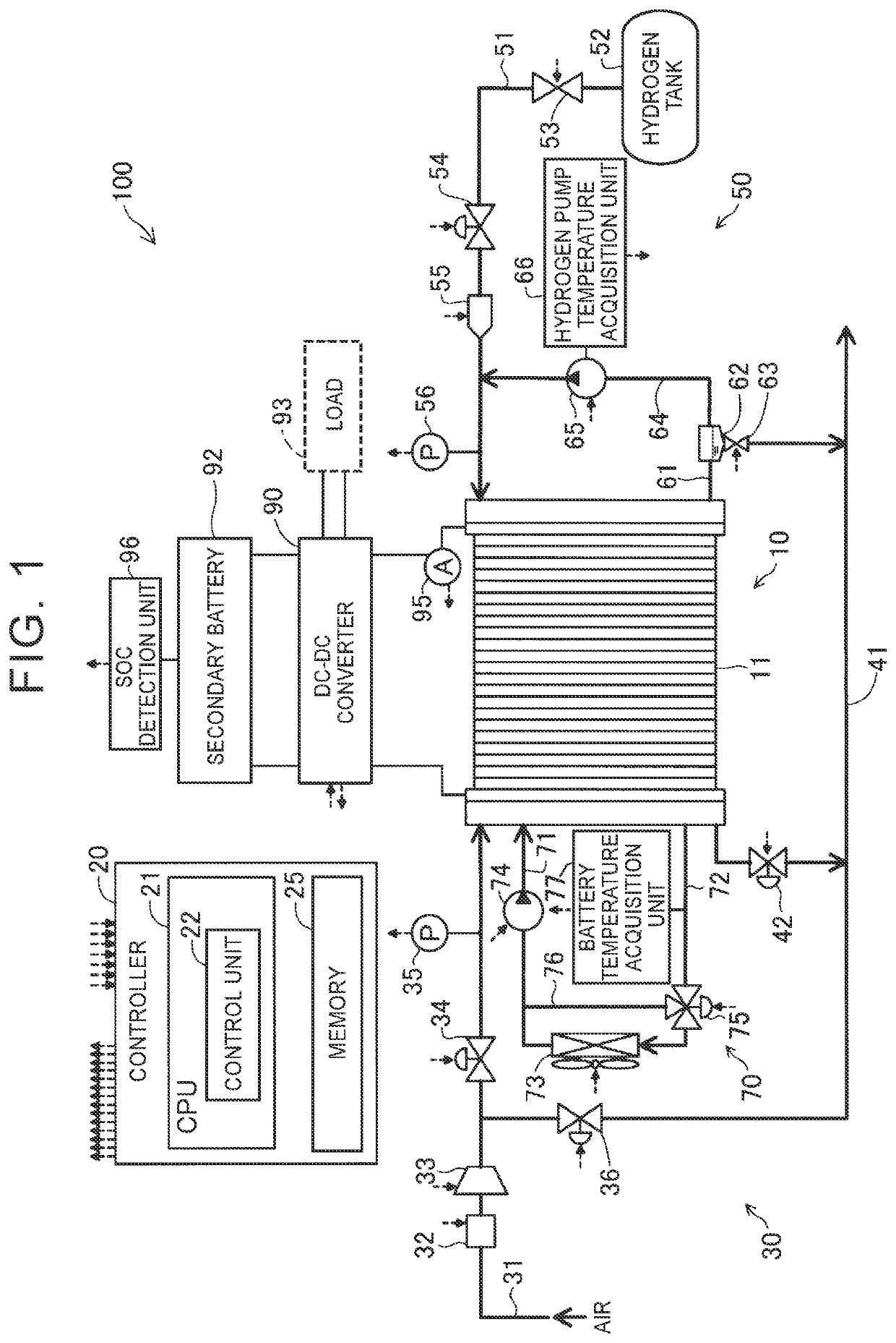
[0013]FIG. 1 is a schematic diagram showing the configuration of a fuel cell system 100 that is one embodiment of the disclosure. The fuel cell system 100 is mounted on, for example, a vehicle. The fuel cell system 100 outputs electric power that is a power source of the vehicle in response to a request from a driver. The fuel cell system 100 includes a fuel cell 10, an oxidant gas supply and exhaust unit 30, a fuel gas supply and exhaust unit 50, a cooling medium circulation unit 70, and a controller 20. The fuel cell system 100 further includes a DC-DC converter 90 and a secondary battery 92.

[0014]The fuel cell 10 is a polymer electrolyte fuel cell that generates electric power upon receiving hydrogen gas and air supplied as reactant gases. The fuel cell 10 has a stacking structure in which a plurality of cells 11 is stacked on top of each other. Although not shown in the diagram, each cell 11 includes a membrane electrode as...

second embodiment

B. Second Embodiment

[0050]The fuel cell system 100 in a second embodiment is similar to the fuel cell system 100 in the first embodiment shown in FIG. 1, so the detailed description thereof is omitted.

[0051]FIG. 3 is a flowchart showing the procedure of a scavenging operation in the second embodiment. The scavenging operation in the second embodiment differs from the scavenging operation in the first embodiment shown in FIG. 2 in that the procedure after completion of step S135 is modified and step S137 is added. The remaining procedure of the scavenging operation of the second embodiment is the same as the scavenging operation of the first embodiment, so like step numbers denote the same steps, and the detailed description thereof is omitted.

[0052]As shown in FIG. 3, when the warm-up operation is performed (step S135), the process returns to step S125. Until it is determined that the SOC of the secondary battery 92 is higher than or equal to the threshold (70%) as a result of charg...

third embodiment

C. Third Embodiment

[0055]The fuel cell system 100 in a third embodiment is similar to the fuel cell system 100 in the first embodiment shown in FIG. 1, so the detailed description thereof is omitted.

[0056]FIG. 4 is a flowchart showing the procedure of a scavenging operation in the third embodiment. The scavenging operation in the third embodiment differs from the scavenging operation in the first embodiment shown in FIG. 2 in that step S140 and step S145 are omitted. The remaining procedure of the scavenging operation of the third embodiment is the same as the scavenging operation of the first embodiment, so like step numbers denote the same steps, and the detailed description thereof is omitted.

[0057]As shown in FIG. 4, when it is determined in step S130 that the SOC is higher than or equal to the threshold (70%) (YES in step S130), step S155 and step S160 are executed.

[0058]With the fuel cell system 100 having the above configuration according to the third embodiment, when the tem...


PUM


Abstract

A fuel cell system includes a component in a circulation passage for off-gas, a battery temperature acquisition unit configured to acquire a fuel cell temperature, a component temperature acquisition unit configured to acquire a component temperature, a state-of-charge acquisition unit configured to acquire a state of charge of a secondary battery, and a controller configured to, when a temperature difference between the acquired fuel cell temperature and the acquired component temperature is greater than or equal to a predetermined temperature difference at the time of a stop of power generation of the fuel cell system, perform a warm-up operation of a fuel cell and store electric power generated through the warm-up operation in the secondary battery while the state of charge of the secondary battery is lower than a predetermined state of charge, and, after completion of the warm-up operation, perform the scavenging operation at predetermined scavenging power.

Description

INCORPORATION BY REFERENCE[0001]The disclosure of Japanese Patent Application No. 2018-139949 filed on Jul. 26, 2018 including the specification, drawings and abstract is incorporated herein by reference in its entirety.BACKGROUND1. Technical Field[0002]The disclosure relates to a fuel cell system.2. Description of Related Art[0003]Water produced during operation, water for humidifying reactant gas, and other water are present inside a fuel cell. When the temperature of a fuel cell decreases to below-freezing temperature after a stop of the operation of the fuel cell, water remaining inside the fuel cell, for example, in pores of a catalyst layer or gas diffusion layer in a single cell freezes and limits a flow of reactant gas or off-gas at next startup. For this reason, a fuel cell system that performs a scavenging operation after a stop of the fuel cell has been suggested. In a fuel cell system described in Japanese Unexamined Patent Application Publication No. 2017-010908 (JP 201...

Claims


Application Information

Patent Timeline
IPC IPC(8): H01M8/0432H01M8/04029H01M8/04082H01M8/04228H01M8/04701H01M8/04746H01M8/04119G01R31/3842B60L58/12
CPCH01M2250/20B60L58/12H01M8/04228H01M8/04365H01M8/04753G01R31/3842H01M8/04029H01M8/04731H01M8/04201H01M8/04373H01M8/04164H01M8/04253H01M8/04303H01M8/04097H01M8/0435H01M8/04231H01M16/006B60L3/0053B60L50/75B60L58/40B60L58/32B60L58/33B60L2240/545Y02T90/40Y02T10/70Y02E60/50Y02E60/10
Inventor TAKAHASHI, MANABU
Owner TOYOTA JIDOSHA KK
Features
  • R&D
  • Intellectual Property
  • Life Sciences
  • Materials
  • Tech Scout
  • Unparalleled Data Quality
  • Higher Quality Content
  • 60% Fewer Hallucinations
Learn More