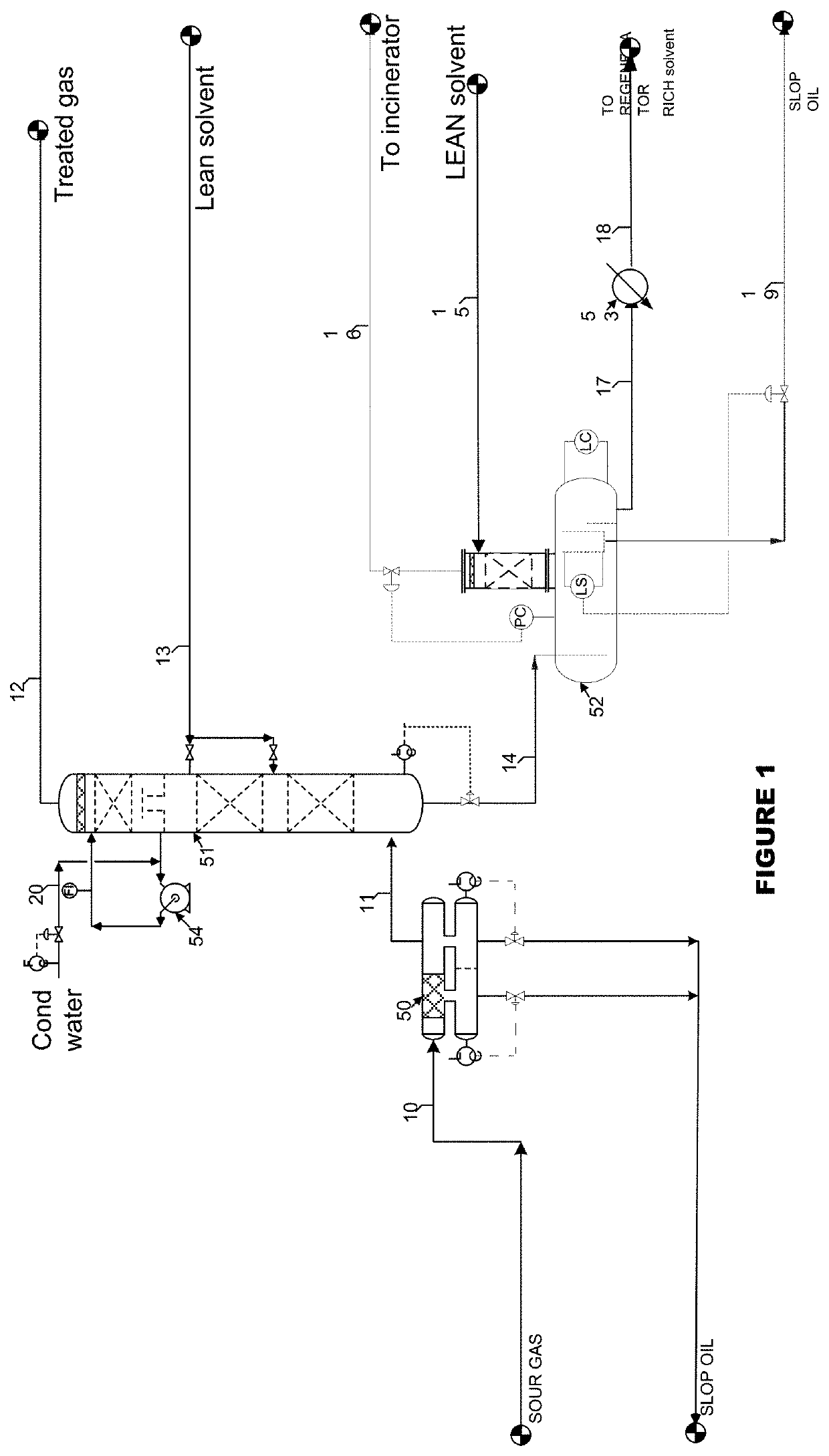
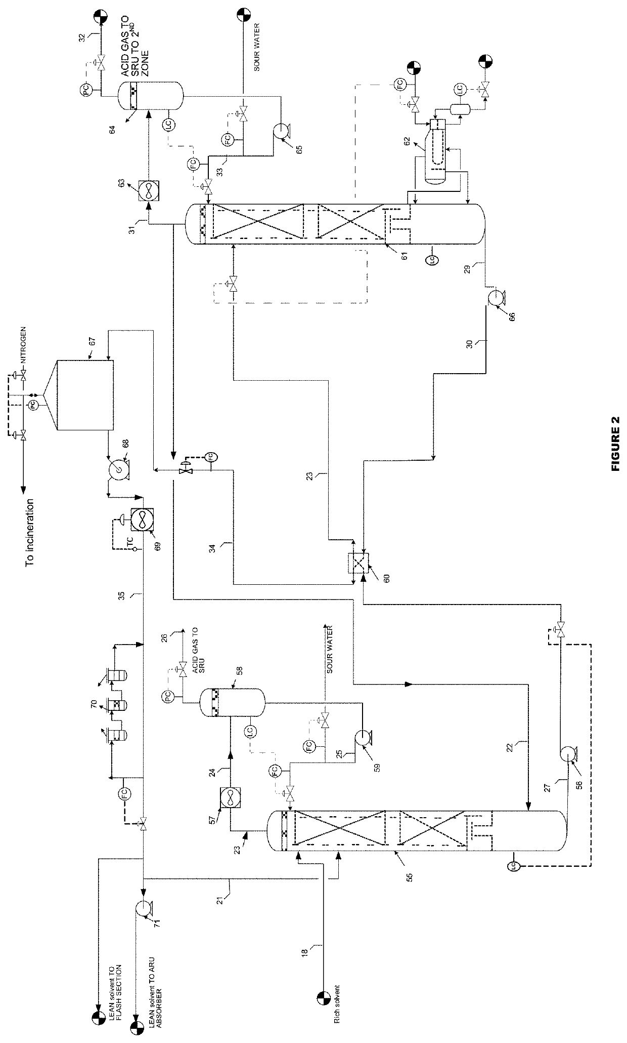
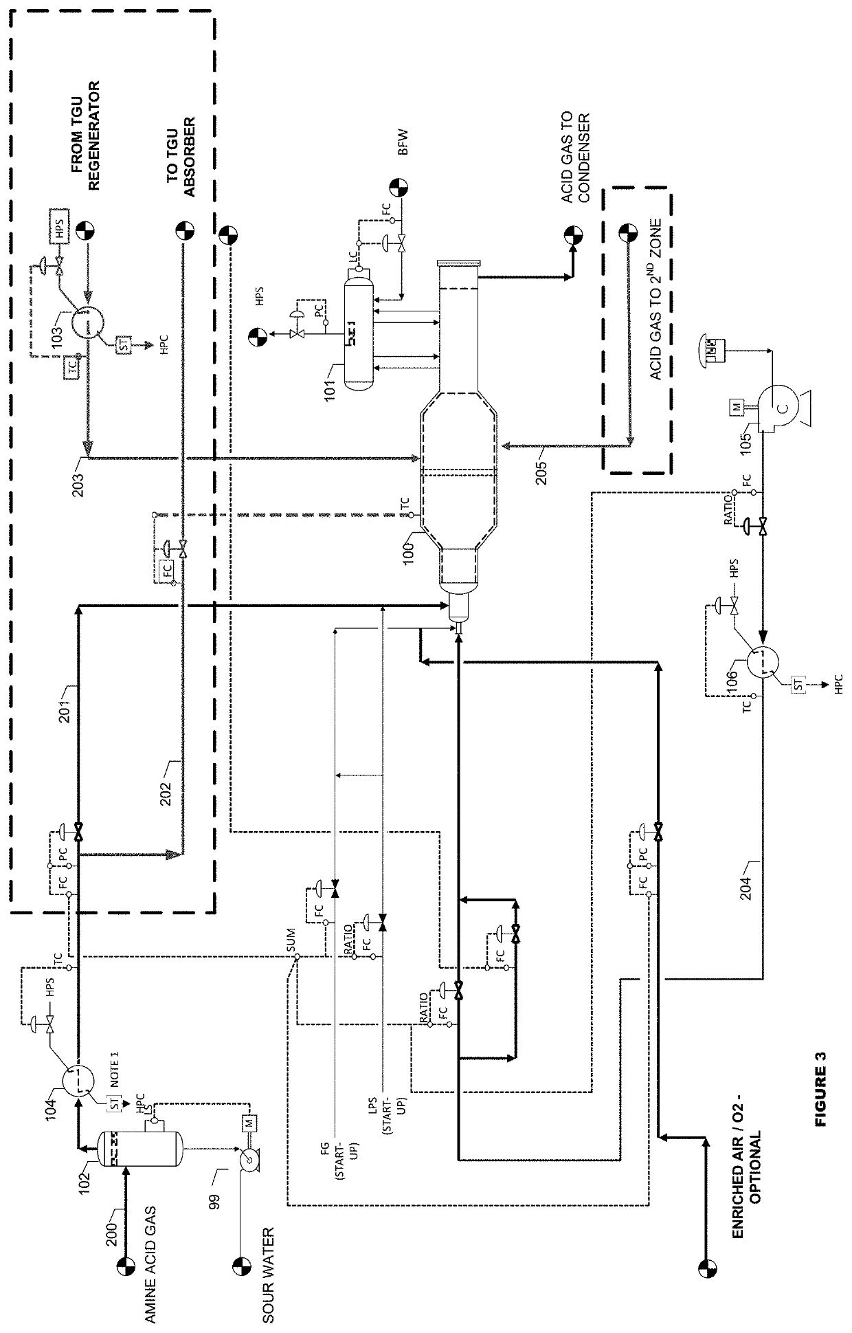
“enrich-smax” - integrated h2s removal, separation of impurities and partial acid gas enrichment in sour gas processing

a technology of acid gas enrichment and sour gas treatment, which is applied in the direction of sulfur preparation/purification, separation processes, energy input, etc., can solve the problems of hydrocarbon destruction as impurities and waste, the economics of producing pipe lines, and the inability to reduce the sru

Active Publication Date: 2020-02-06
SANTO STEPHEN L +1
View PDF1 Cites 3 Cited by
  • Summary
  • Abstract
  • Description
  • Claims
  • Application Information

AI Technical Summary

Benefits of technology

[0046]The 2-zone reaction furnace is equipped with Choke Ring, Checker Wall, Vector Wall or equivalent to work as the divider, to create turbulent velocity and to protect any radiation to the tube sheet of the waste heat boiler.

Problems solved by technology

In some cases the acid gas composition in these reserves is very high and economics of producing pipe line quality gas are marginal.
If hydrocarbon is not recovered the acid gas from the primary regeneration overhead flows to the sulfur recovery unit and hydrocarbons will be destructed as impurities and wasted where if it is recovered could be used as fuel gas to save energy.
In this project, we had high H2S / CO2 ratio and CO2 slip will decline therefore, the SRU will not be smaller and the acid gas enrichment are not very effective.
In other words, after a detailed evaluation, we concluded that adding conventional acid gas enrichment would be not as effective as generally expected.

Method used


Image

  • “enrich-smax” - integrated h2s removal, separation of impurities and partial acid gas enrichment in sour gas processing
  • “enrich-smax” - integrated h2s removal, separation of impurities and partial acid gas enrichment in sour gas processing
  • “enrich-smax” - integrated h2s removal, separation of impurities and partial acid gas enrichment in sour gas processing

Examples


Embodiment Construction

[0058]One or more illustrative embodiments incorporating the invention disclosed herein are presented below. Not all features of an actual implementation are described or shown in this application for the sake of clarity. It is understood that in the development of an actual embodiment incorporating the present invention, numerous implementation-specific decisions must be made to achieve the developer's goals, such as compliance with system-related, business-related, government related and other constraints, which vary by implementation and from time to time. While a developer's efforts might be complex and time-consuming, such efforts would be, nevertheless, a routine undertaking for those of ordinary skill the art having benefit of this disclosure.

[0059]In the discussion of the Figures, the same or similar numbers will be used throughout to refer to the same or similar components. Not all valves and the like necessary for the performance of the process have been shown in the inter...


PUM

PropertyMeasurementUnit
operating pressureaaaaaaaaaa
temperatureaaaaaaaaaa

Abstract

This disclosure relates generally to processes sour gas treating for H2S Removal, separation of impurities such as hydrocarbons, BTEX and mercaptans and the Partial Acid Gas Enrichment integrated system from the sour gas field developments, or any application. The combination of innovation schemes comprises one or more absorbers, primary and secondary regenerators. The secondary regenerator functions are, enriching the H2S stream further and to separate the hydrocarbons, mercaptans and BTEX where an additional acid gas enrichment and hydrocarbons removal could be eliminated. Then there is a unique sulfur recovery and tail gas treating with a unique 2-zone reaction furnace, tail gas absorber which operated as partial acid gas enrichment by receiving split acid gas from the SRU and the hydrolysis reactor to hydrolyze sulfur compounds.
The acid gas from the primary and the secondary amine regeneration and the acid gas recycle from the tail gas which is preheated and these streams flow to the 2-zones reaction furnace in the sulfur recovery unit to establish a stable low emission and higher recovery.

Description

CROSS REFERENCE TO RELATED APPLICATIONS[0001]Not ApplicableSTATEMENT REGARDING FEDERALLY SPONSORED RESEARCH OR DEVELOPMENT[0002]Not ApplicableREFERENCE TO SEQUENCE LISTING[0003]Not ApplicableREFERENCE TO A TABLE[0004]Not ApplicableREFERENCE TO A COMPUTER PROGRAM LISTING COMPACT DISK APPENDIX[0005]Not ApplicableBACKGROUND OF THE INVENTION[0006]This disclosure relates generally to processes sour gas treating for H2S Removal, separation of impurities such as hydrocarbons, BTEX and mercaptans and the Acid Gas Enrichment integrated system from the sour gas field developments, refineries, associated gas, shale gas, SYN GAS from power plants, natural gas processing applications, and early production facility more particularly to processes the mixture of the 100% lean H2S gas stream with impurities such as heavy hydrocarbons, mercaptans, benzene, toluene and Xylene (BTEX). The combination of innovation schemes comprises the H2S Removal and the Acid Gas Enrichment and separation of hydrocarb...

Claims


Application Information

Patent Timeline
Patent Type & Authority Applications(United States)
IPC IPC(8): C01B17/04B01D53/14
CPCB01D2252/204C01B17/0456B01D53/1406B01D53/1418B01D53/1425C01B17/0417B01D53/1462B01D53/526B01D2252/20431B01D2257/304B01D2257/306B01D2257/702B01D2257/7027Y02P20/129Y02P20/151
Inventor RAMESHNI, MAHINSANTO, STEPHENL
Owner SANTO STEPHEN L
Why Eureka
Try Eureka