Coil component and manufacturing method for the same

a manufacturing method and coil technology, applied in the direction of coil manufacturing, inductance with magnetic core, inductance, etc., can solve the problems of reducing the value of moisture entering the exterior, the adhesion force decreases, and the interfacial peeling, so as to reduce the influence of the close contact layer and suppress the decrease of the adhesion strength of the resin insulation layer

Active Publication Date: 2020-02-06
MURATA MFG CO LTD
View PDF9 Cites 0 Cited by
  • Summary
  • Abstract
  • Description
  • Claims
  • Application Information

AI Technical Summary

Benefits of technology

[0005]The present disclosure provides a multilayer body which suppresses interfacial peeling between laminated resin insulation layers.
[0025]In the above-described manufacturing method for the coil component, it is preferable that the close contact layer include one plane or a plurality of small pieces being spaced from each other in a central portion of the spiral-shaped coil conductor layer, and that the manufacturing method further include forming, by laser processing, a through-hole passing through the multilayer body in a lamination direction in the central portion of the spiral-shaped coil conductor layer, and causing the through-hole to be filled with a magnetic material. According to this configuration, a laser beam is scattered by the close contact layer, and the inner diameter of the through-hole formed by the laser beam is increased. With this, since the volume of the magnetic material filling the through-hole increases, it is possible to improve the inductance.

Problems solved by technology

The decrease in the adhesion force may cause interfacial peeling due to a thermal load during the manufacturing process, after the mounting, or the like.
The interfacial peeling may raise a risk that the moisture entering from the exterior decreases a value of insulation resistance between the coil conductor layers or inside the coil conductor layers so that the deterioration in electric characteristics, an operation failure, or the like is caused by a short circuit, an open circuit, or the like.

Method used


Image

  • Coil component and manufacturing method for the same
  • Coil component and manufacturing method for the same
  • Coil component and manufacturing method for the same

Examples


first embodiment

Modification of First Embodiment

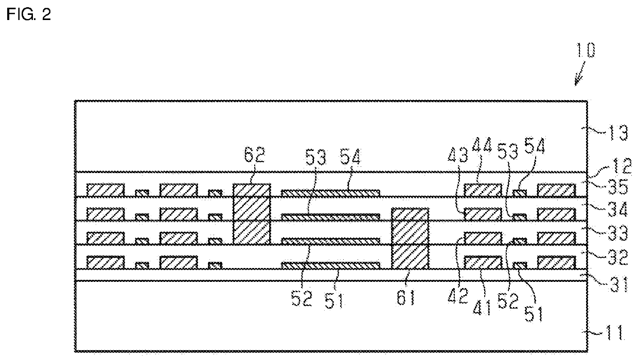
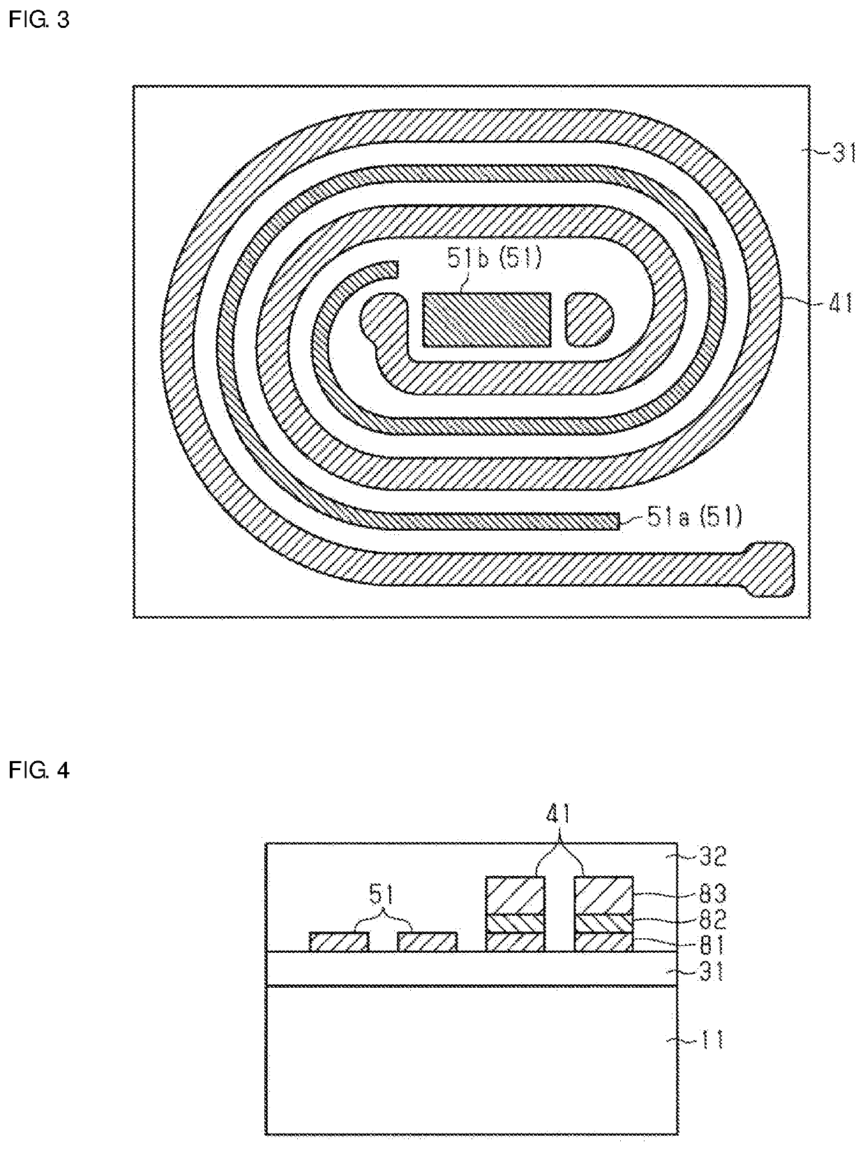
[0095]In the coil component 10, although the close contact layers 51 to 54 include the flat spiral-shaped linear portion 51a continuously formed along the flat spiral-shaped coil conductor layers 41 to 44, the plate-shaped plane 51b formed in the central portion of the coil conductor layers 41 to 44, and the like, the shape of the close contact layers 51 to 54 is not limited thereto.

[0096]As illustrated in FIGS. 9 and 10, in a coil component 10a, close contact layers 51 to 54 are formed of a plurality of small pieces 51c and a plurality of small pieces 51d. As illustrated in FIG. 10, the plurality of small pieces 51c is spaced from each other along a flat spiral-shaped coil conductor layer 41, and is disposed being spaced from the coil conductor layer 41. The plurality of small pieces 51d is spaced from each other and is disposed being spaced from the flat spiral-shaped coil conductor layer 41 in a central portion of the coil conductor layer 41. The p...

second embodiment

Modification of Second Embodiment

[0112]As illustrated in FIGS. 16 and 17, in a case where a close contact layer 51 including a plurality of small pieces 51d is formed, a laser beam 110 is scattered by the plurality of small pieces 51d, whereby a through-hole 12X having a larger diameter can be easily formed.

[0113]Other Modifications

[0114]The above-described embodiments may be carried out in the following modes.

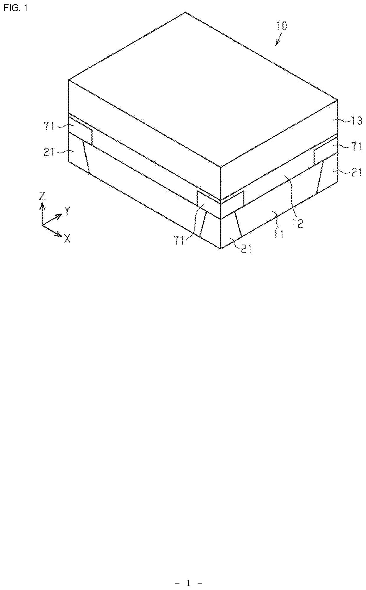
[0115]In the above embodiments, although the coil components 10 and 100 each including two coils are provided, one, three, or more than three coils may be included in the coil component. For example, all the coil conductor layers 41 to 44 of the coil component 10 may be connected in series so as to constitute an inductor component including one coil. There is no limitation on the number of coil conductor layers, and it is sufficient that at least one contact surface between a resin insulation layer and a close contact layer is present. Although the coil conductor layer has a f...


PUM

PropertyMeasurementUnit
thicknessaaaaaaaaaa
thicknessaaaaaaaaaa
thicknessaaaaaaaaaa

Abstract

A coil component includes a multilayer body in which a plurality of resin insulation layers is laminated, a spiral-shaped coil conductor layer disposed on main surface of one of the resin insulation layers, and a close contact layer disposed at interfaces between two of the resin insulation layers and not connected to the coil conductor layer. The close contact layer contains a metal having desired adhesion to the resin insulation layers.

Description

CROSS-REFERENCE TO RELATED APPLICATION[0001]This application claims benefit of priority to Japanese Patent Application No. 2018-144834, filed Aug. 1, 2018, the entire content of which is incorporated herein by reference.BACKGROUNDTechnical Field[0002]The present disclosure relates to a coil component and a manufacturing method for the same.Background Art[0003]Electronic components have been mounted on various electronic apparatuses. As one of the electronic components, for example, a multilayer coil component is known as described, for example, Japanese Unexamined Patent Application Publication No. 2014-127718. A multilayer inductor component includes a base body on which a plurality of insulation layers is laminated, and a coil conductor layer wound on a main surface of the insulation layer.SUMMARY[0004]It is noted that, in the above-mentioned inductor component, adhesion strength between the laminated insulation layers may decrease due to a residue of the resist or the like used i...

Claims


Application Information

Patent Timeline
Patent Type & Authority Applications(United States)
IPC IPC(8): H01F27/28H01F27/32H01F41/04H01F41/12
CPCH01F27/2804H01F41/122H01F2027/2809H01F41/041H01F27/323H01F27/306H01F17/0013H01F17/04H01F41/042
Inventor ANNEN, KAZUNORI
Owner MURATA MFG CO LTD
Why Eureka
Try Eureka