Pouch Film and Method for Manufacturing the Same

Pending Publication Date: 2020-02-06
LG ENERGY SOLUTION LTD
4 Cites 0 Cited by

AI-Extracted Technical Summary

Problems solved by technology

However, the pouch of the secondary battery according to the related art has low flexibility.
As a result, when the pouch is bent several times, the pouch may be cut or broken.
However, there has been a problem that moisture and other foreign substances are ea...

Benefits of technology

[0025]The embodiments of the present invention may have at least the following effects.
[0026]The pouch may be improved in flexibility, waterproofness, and electrolyte resistance.
[0027]Also, the pouch m...

Abstract

A method for a pouch film according to an embodiment of the present invention includes: a step of applying an adhesive on one surface of a first polymer layer; a step of depositing metal particles on the adhesive; a step of applying heat and a pressure to the deposited metal particles to sinter the metal particles and thereby forming a gas barrier layer; and a step of laminating a second polymer layer on one surface of the gas barrier layer.

Application Domain

Technology Topic

Image

  • Pouch Film and Method for Manufacturing the Same
  • Pouch Film and Method for Manufacturing the Same
  • Pouch Film and Method for Manufacturing the Same

Examples

  • Experimental program(2)

Example

Manufacturing Example 1
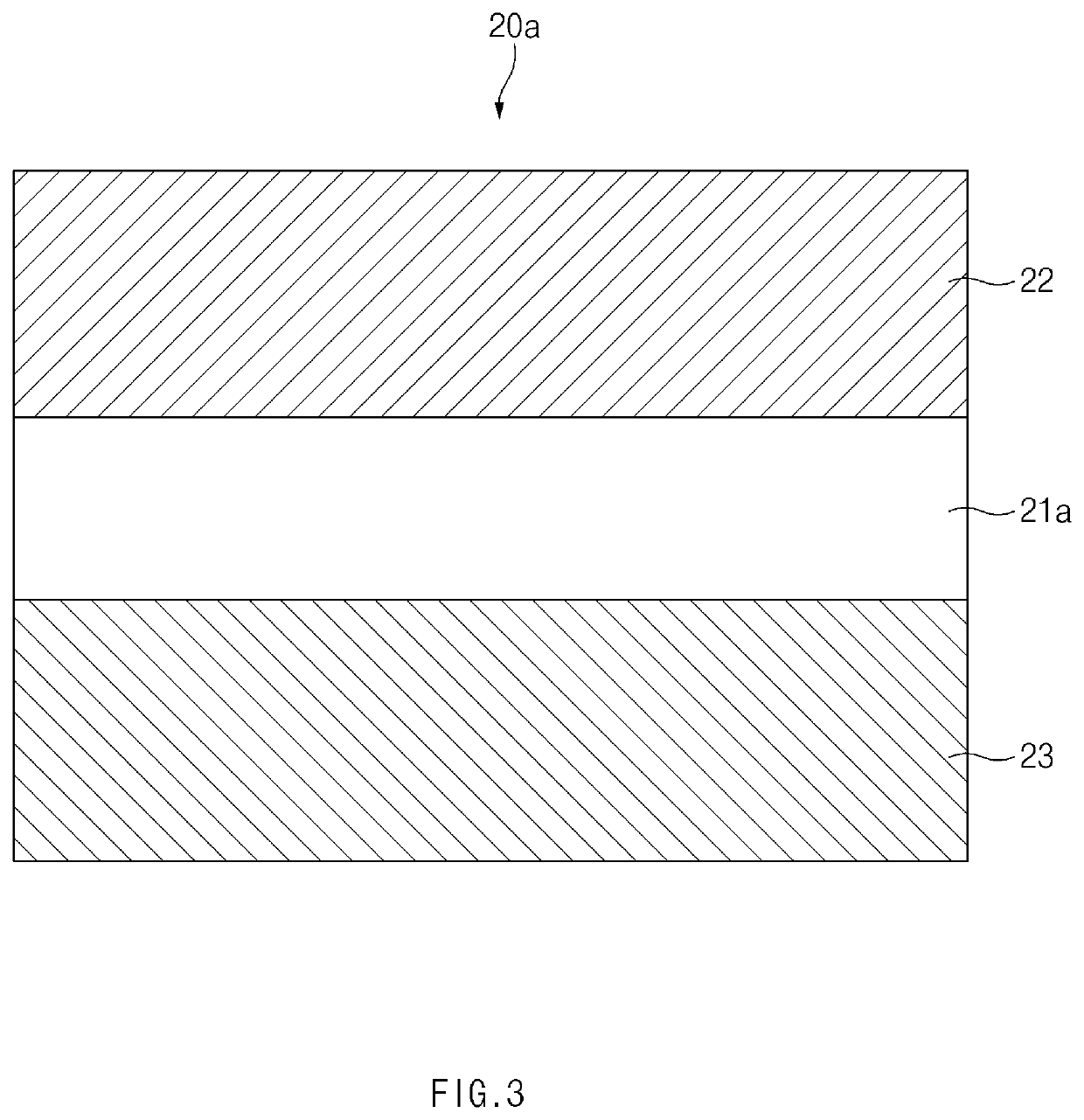
[0092]An adhesive was applied to one surface of a surface protection layer made of polyethylene terephthalate (PET), and aluminum (Al) metal particles, each of which has a diameter of 0.1 μm to 10 μm were deposited by using a plasma atomization method. Thereafter, a temperature of 150° C. and a pressure of 200 MPa were maintained, and the metal particles were sintered by using a pressure sintering method to form a gas barrier layer. Here, the formed gas barrier layer was measured to a thickness of 10 μm. Then, an adhesive was applied on one surface of the gas barrier layer, and a sealant layer made of polypropylene (PP) was laminated to manufacture a pouch film.
Comparative Manufacturing Example 1
[0093]An adhesive was applied to one surface of a surface protection layer made of polyethylene terephthalate (PET), an aluminum foil (Al foil) having a thickness of 15 μm was laminated on the adhesive on the one side of the surface protection layer, an adhesive was applied on the aluminum thin film, and a sealant layer made of polypropylene (PP) is laminated to manufacture a pouch film having the structure of FIG. 3.

Example

Comparative Manufacturing Example 2
[0094]A pouch film was manufactured through the same manner as Manufacturing Example 1, except that the sintering process was not performed after depositing the metal particles. The pouch film manufactured as described above has the structure of FIG. 13.
[0095]The physical properties of the pouch films manufactured through Manufacturing Example 1 and Comparative Manufacturing Examples 1 and 2 were measured by following methods. The measurement results were shown in Table 1 below.
[0096]Physical Property
[0097]1. Flexibility
[0098]A bending test was performed as described below to measure flexibility. First, each of the pouch films manufactured through Manufacturing Example 1 and Comparative Manufacturing Examples 1 and 2 was cut to a size of 15 mm×150 mm. Then, one side of each of the pouch films was fixed to an upper jig of an MIT folding endurance tester, and the other side of each of the pouch films was fixed to a lower fixing jig (a tip has a curvature radius of 0.1 mm and a load of 250 g). Also, the pouch films were repeatedly bent at an angle of ±90° and at the same speed of 175 cpm. After repeating the bending, LED light was irradiated to each of the pouch films to measure the number of times of bending immediately before pinholes are generated.
[0099]2. Electrolyte Resistance
[0100]Each of the pouch films manufactured through Manufacturing Example 1 and Comparative Manufacturing Examples 1 and 2 was cut to a size of 25 mm×100 mm. Then, 80 ml of an electrolyte (1 M of lithium salt (LiPF6) and a mixture, in which ethylene carbonate (EC)):ethyl methyl carbonate (EMC):dimethyl carbonate (DMC) are mixed at a ratio of 3:3:4, are melted) and the pouch films were accommodated in a Nalgene bottle having a capacity of 125 ml and then sealed with paraffin. The Nalgene bottle was sealed with an aluminum wrapper and stored at a temperature of 85° C. for 24 hours. Then, the pouch films were taken out and rinsed in water, and the water was completely removed. Also, each of the pouch films was cut by a width of 5 mm from both sides thereof to manufacture a sample having a size of 15 mm×100 mm. Then, a surface protection layer of the sample was sheathed, repeatedly bent, and cut up to a gas barrier layer. Then, the sample was pulled toward both sides to delaminate a portion of the sealant layer so that the portion of the sealant layer is exposed. The delaminated sealant layer was fixed to an upper jig of a universal testing machine (UTM), and the remaining portion was attached to a slide glass by using a double-sided tape and then fixed to a lower jig. Thereafter, force required to delaminate the sealant layer and the gas barrier layer was measured under conditions of a delamination rate of 50 mm/min, a grip gap of 80 mm, and a test distance of 30 nm, and the measured force was evaluated as adhesion strength.
[0101]3. Water Vapor Transmission Rate (WVRT)
[0102]Each of the pouch films manufactured through Manufacturing Example 1 and Comparative Manufacturing Examples 1 and 2 was cut to a size of 108 mm×108 mm and mounted in a WVRT tester. Then, a dry nitrogen gas which does not contain water vapor was introduced into one surface of the pouch film, and the water vapor was introduced into the other surface of the pouch film. Here, the two spaces into which the gases are respectively introduced were isolated from each other so that the gases introduced into both the surfaces of the pouch film are not mixed with each other. During the experiment, the temperature was set and maintained at 38° C., and the humidity was set and maintained at 100% RH. Also, an amount of water vapor was measured on the above-mentioned surface into which the dried nitrogen gas is introduced by using a humidity sensor for 24 hours. The amount of water vapor was divided by an area of the surface, and the amount of water vapor per unit area, which passes through the pouch film for 24 hours, was deduced and evaluated by the WVRT.
TABLE 1 Comparative Comparative Manufacturing Manufacturing Manufacturing Example 1 Example 1 Example 2 Flexibility 170 30 200 [times] Adhesion 3.3 6.2 Not measurable Strength [N/15 mm] WVTR [g/m2 · day] 8.06 × 10⁻³ 9.6 × 10⁻⁴ 1.2 × 10⁻²
[0103]As shown in Table 1 above, the pouch film according to Manufacturing Example 1 was not damaged until the bending test is performed up to 170 times, the pouch film according to Comparative Manufacturing Example 1 was not damaged until the bending test is performed up to 30 times, and the pouch film according to Comparative Manufacturing Example 2 was not damaged until the bending test is performed up to 200 times. Thus, it is seen that the pouch film according to Manufacturing Example 1 is much more flexible than that of the pouch film according to Comparative Manufacturing Example 1.
[0104]Also, the bonding strength of the pouch film according to Manufacturing Example 1 was 3.3 N/15 mm, and the bonding strength of the pouch film according to Comparative Manufacturing Example 1 was 6.2 N/15 mm. However, in the pouch film according to Comparative Manufacturing Example 2, the gas barrier layer was corroded by the electrolytic, and thus, the measurement was impossible. Thus, it is seen that the pouch film according to Manufacturing Example 1 is much more electrolyte resistance than that of the pouch film according to Comparative Manufacturing Example 1.
[0105]Also, the pouch film according to Manufacturing Example 1 had a WVTR of 8.06×10⁻³ g/m2·day, the pouch film according to Comparative Manufacturing Example 1 had a WVTR of 9.6×10⁻⁴ g/m2·day, and the pouch film according to Comparative Manufacturing Example 2 had a WVTR of 1.2×10⁻² g/m2·day. Thus, it is seen that the pouch film according to Manufacturing Example 1 is much more waterproof property than that of the pouch film according to Comparative Manufacturing Example 1. As described above, when the metal particles are simply deposited without being sintered, too much pores were generated between the metal particles of the pouch film according to Comparative Manufacturing Example 2, and thus, the electrolytic and moisture were easily permeated. However, the pouch film according to Manufacturing Example 1 may be improved in waterproof property and electrolyte resistance by sintering the metal particles to reduce the number of gaps between the gas barrier layers.
[0106]Therefore, it is seen that the pouch film according to an embodiment of the present invention is superior to the pouch film according to the related art in flexibility, water resistance and electrolyte resistance of the pouch.
[0107]Those with ordinary skill in the technical field of the present invention pertains will be understood that the present invention can be carried out in other specific forms without changing the technical idea or essential features. Therefore, the above-disclosed embodiments are to be considered illustrative and not restrictive. Accordingly, the scope of the present invention is defined by the appended claims rather than the foregoing description and the exemplary embodiments described therein. Various modifications made within the meaning of an equivalent of the claims of the invention and within the claims are to be regarded to be in the scope of the present invention.

PUM

PropertyMeasurementUnit
Temperature50.0°C
Temperature200.0°C
Temperature85.0°C
tensileMPa
Particle sizePa
strength10

Description & Claims & Application Information

We can also present the details of the Description, Claims and Application information to help users get a comprehensive understanding of the technical details of the patent, such as background art, summary of invention, brief description of drawings, description of embodiments, and other original content. On the other hand, users can also determine the specific scope of protection of the technology through the list of claims; as well as understand the changes in the life cycle of the technology with the presentation of the patent timeline. Login to view more.

Similar technology patents

Classification and recommendation of technical efficacy words

Why Eureka
Try Eureka