Signal combining device and signal combining method
a technology of signal combining and combining device, which is applied in the direction of transmission monitoring, satellite communication transmission, electromagnetic transmission, etc., can solve the problems of limiting the use of microwave communication for increasing the capacity of the communication system, affecting the accuracy of signal combining, etc., to achieve the effect of high speed and high accuracy
- Summary
- Abstract
- Description
- Claims
- Application Information
AI Technical Summary
Benefits of technology
Problems solved by technology
Method used
Image

Examples
first example embodiment
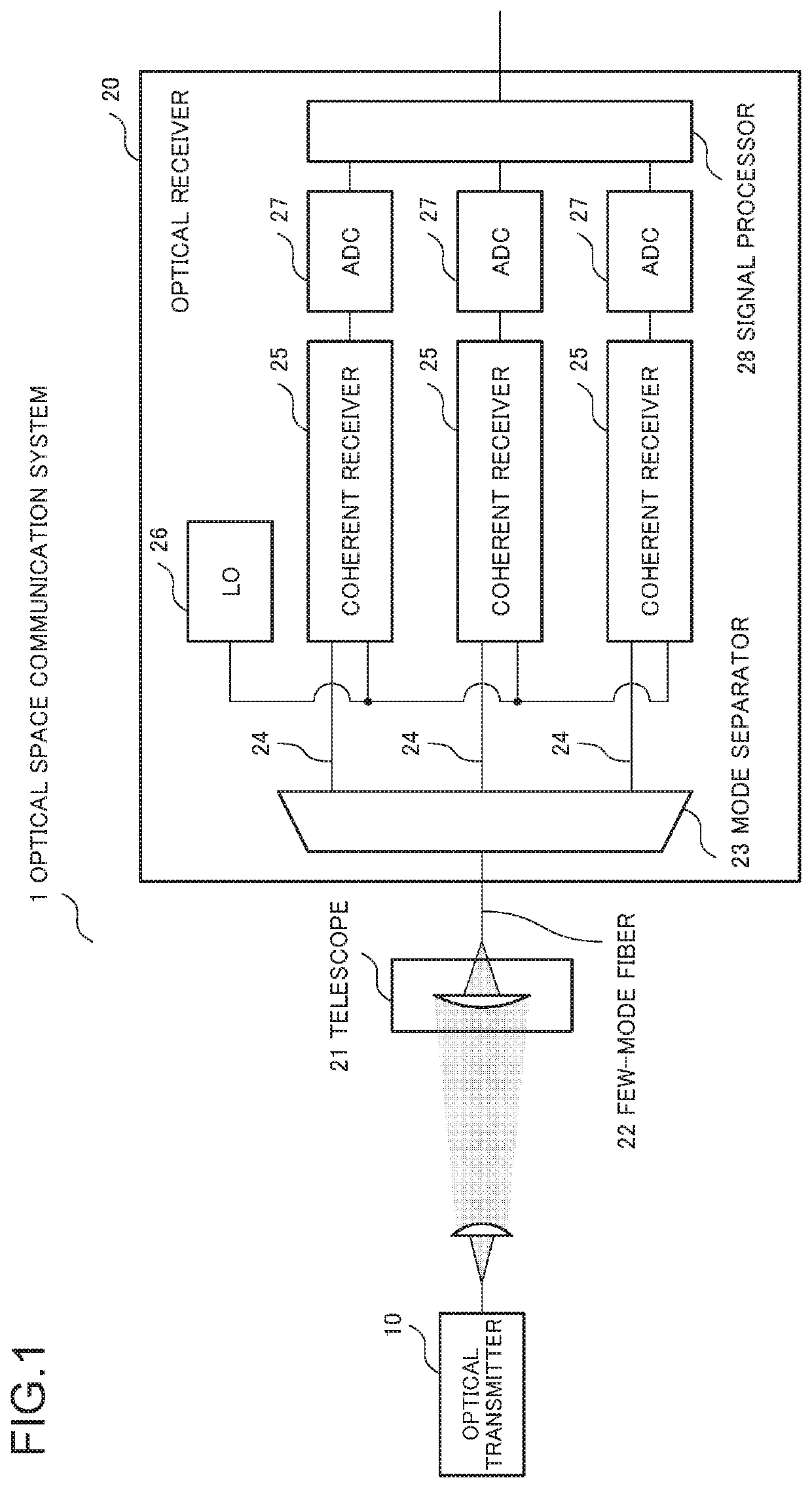
[0048]FIG. 1 is a diagram illustrating a configuration example of an optical space communication system 1 according to a first example embodiment of the present invention. The optical space communication system 1 is an optical communication system using a diversity combination digital signal processing, and includes an optical transmitter 10 and an optical receiver 20. The optical transmitter 10 transmits a single optical signal, and the optical receiver 20 receives the optical signal propagating through an atmosphere.
[0049]The optical receiver 20 is an optical receiver of a mode diversity type, and includes a telescope 21, a few-mode fiber (FMF) 22, a mode separator 23, and single-mode fibers (SMFs) 24.
The optical receiver 20 further includes coherent receivers 25, a local oscillator (LO) 26, analog-to-digital converters (ADCs) 27, and a signal processor 28.
[0050]The telescope 21 includes a lens, and couples received optical signals to the few-mode fiber 22. The mode separator 23 f...
second example embodiment
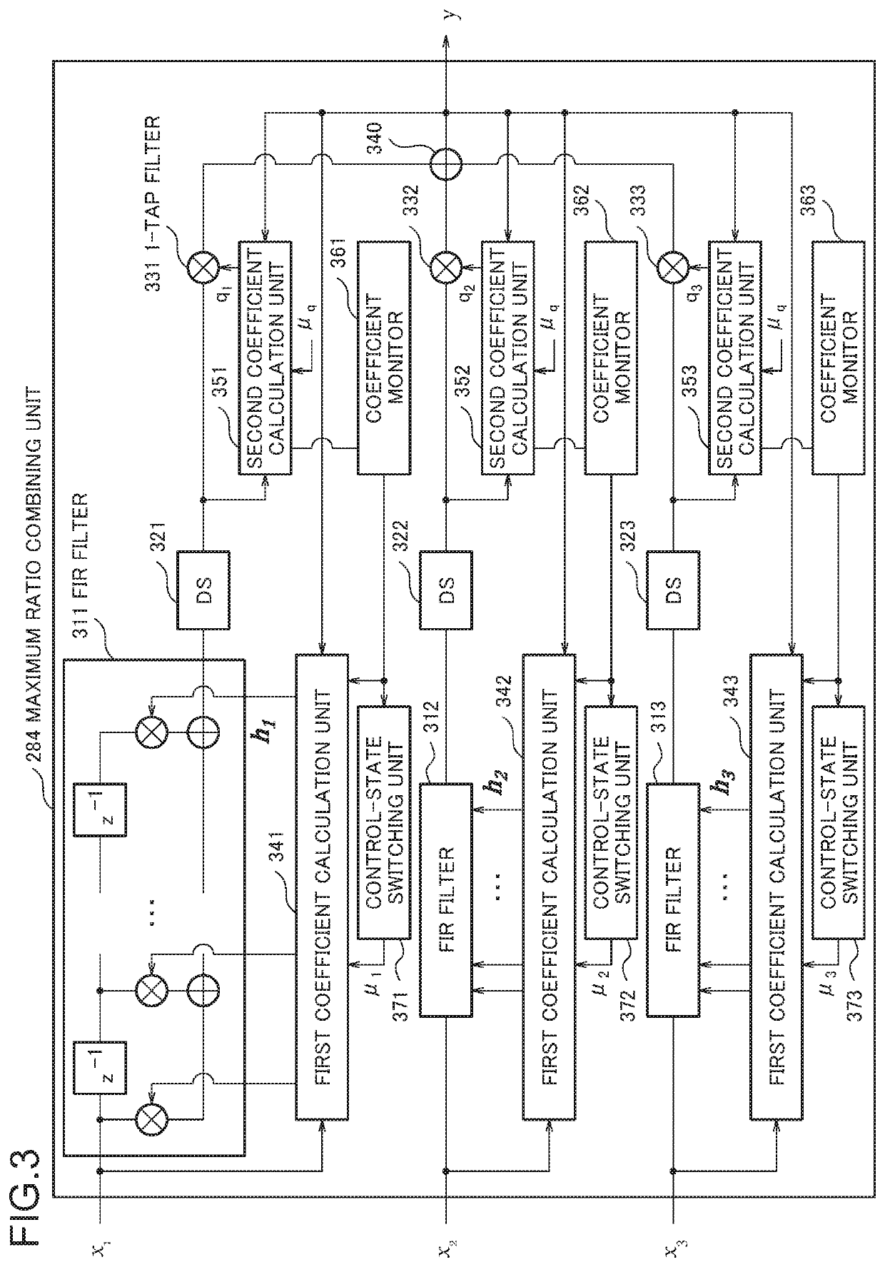
[0080]In the first example embodiment, the FIR filters of the reception branches are used as the filters for compensating for characteristics of the static filters or the transmitting / receiving devices that change only at low speed. Further, the 1-tap filters are used for calculating the weightings for maximum ratio combining that follows high-speed SNR fluctuation of the reception branches due to atmospheric fluctuation. Thus, the step size for updating the second coefficients are set larger than the step size for updating the first coefficient, and the procedure of updating the first coefficients of the reception branches is switched based on the magnitudes of the second coefficients of the reception branches.
[0081]In a second example embodiment of the present invention, a condition for intensity normalization of the filter coefficients is added to the adaptive control for the first coefficients in such a way that the functions of the first coefficients and the second coefficients...
third example embodiment
[0086]FIG. 8 is a block diagram illustrating a configuration example of a signal combining device 50 according to a third example embodiment. The maximum ratio combining unit 284 described in the first and second example embodiments can be also referred to as the signal combining device 50 described below.
[0087]The signal combining device 50 includes a plurality of first filters 51, a plurality of second filters 52, a combiner 53, and a controller 54. The first filters 51 subject a plurality of reception signals, which are generated by subjecting optical signals to coherent detection, to processing performed with first filter coefficients. The second filters 52 subject the outputs of the first filters 51 to processing performed with second filter coefficients. The combiner 53 functions as a combination means for outputting combined signals obtain by combining outputs of the second filters. The combiner 53 is, for example, an adder. The controller 54 functions as a control means for ...
PUM
 Abstract
Description
Claims
Application Information
 - R&D
- Intellectual Property
- Life Sciences
- Materials
- Tech Scout
- Unparalleled Data Quality
- Higher Quality Content
- 60% Fewer Hallucinations
Browse by: Latest US Patents, China's latest patents, Technical Efficacy Thesaurus, Application Domain, Technology Topic, Popular Technical Reports.
© 2025 PatSnap. All rights reserved.Legal|Privacy policy|Modern Slavery Act Transparency Statement|Sitemap|About US| Contact US: help@patsnap.com