Variable vacuum capacitor and cooling method
a vacuum capacitor and capacitor technology, applied in capacitors, air/gas/vacuum dielectric ipc5, capacitors, etc., can solve the problem of not being able to control the cooling arrangement of prior art capacitors in this way, and achieve the effect of extending the maximum power of the device and/or the life of the device, extending the maximum power of the device and/or the maximum temperature rang
- Summary
- Abstract
- Description
- Claims
- Application Information
AI Technical Summary
Benefits of technology
Problems solved by technology
Method used
Image

Examples
first embodiment
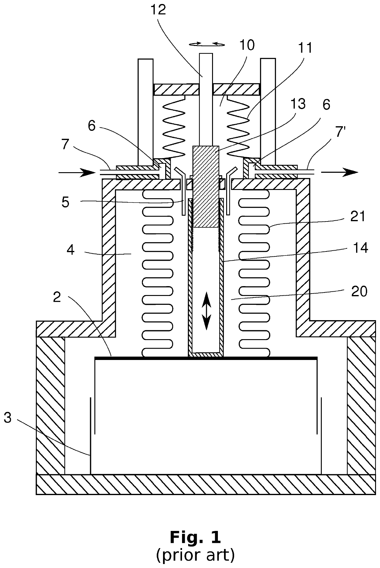
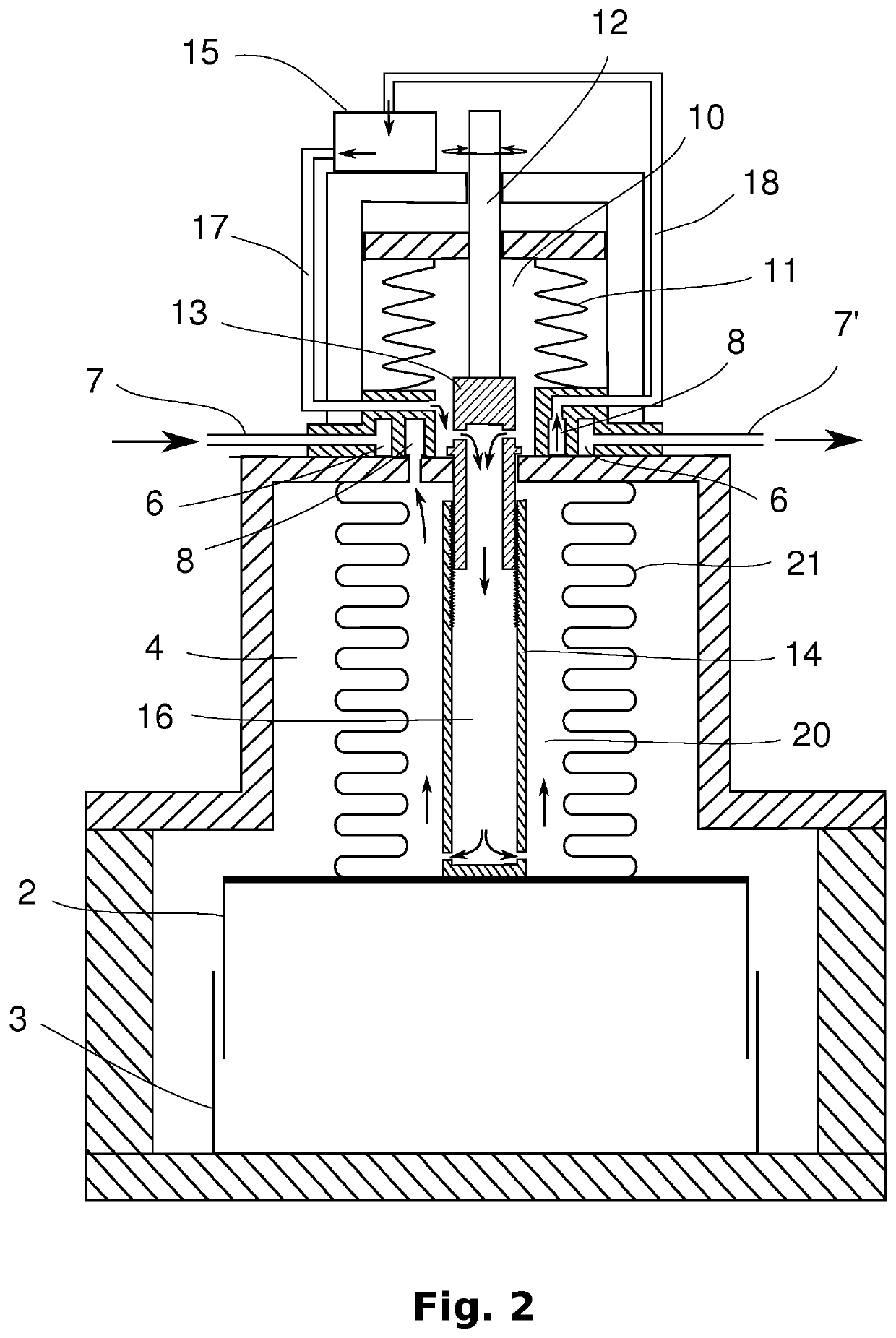
[0015]FIG. 2 shows a highly simplified schematic cross-section view of a variable vacuum capacitor according to the invention. A heat transfer fluid such as an oil, fills the main bellows 21 and the expansion bellows 11, as in the prior art capacitor shown in FIG. 1. Coolant, such as water, is passed through a coolant circuit from coolant inlet 7, through one or more coolant heat exchange channels 6, to coolant outlet 7′. A heat transfer fluid circuit is provided for circulating the heat transfer fluid (eg oil) through heat exchange channels 8 of the heat exchanger, such that heat is transferred from the oil to the water.
[0016]The oil is circulated through the heat transfer fluid circuit by means of a pump 15 or similar fluid propulsion means. From the pump 15, the oil circulates through feed conduit 17 and passes through one or more openings in the proximal region of the capacitor drive shaft 13, 14—preferably in the axially static part 13 of the shaft which engages with the axiall...
second embodiment
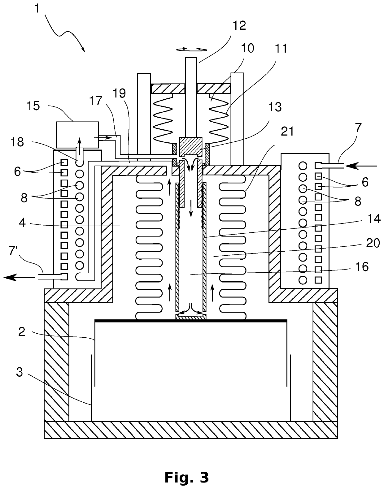
[0018]FIG. 3 shows the invention, in which the heat transfer fluid which is heated while being circulated through the bellows is pumped through a more extensive heat exchange matrix. The coolant (eg water) channels of the matrix are illustrated as square section channels 6, and the heat transfer fluid channels are illustrated as round section channels 8. These shapes are chosen purely for illustration purposes, to help distinguish between the two separate heat exchange circuits; such a difference would normally not be present in a real implementation. The extensive heat exchange matrix illustrated in FIG. 3 is bulkier than the simple heat exchanger arrangement illustrated in FIG. 2, and can advantageously be formed as a jacket around the outer surface of the capacitor's vacuum chamber, as shown. This allows a much greater cooling capacity, and therefore a much higher operating power of the capacitor, but without increasing the capacitor's physical footprint. This allows the inventiv...
PUM
 Abstract
Description
Claims
Application Information