Powder bed fusion apparatus and methods

a technology of fusion apparatus and powder bed, which is applied in the direction of additive manufacturing processes, manufacturing tools, manufacturing environment conditioning, etc., can solve the problems deformation of seals used to seal the gap between the build platform and the side walls, and failure of high build temperature, so as to facilitate the cooling of powder bed and/or the object, the effect of reducing heat transfer

Inactive Publication Date: 2020-02-27
RENISHAW PLC
View PDF0 Cites 12 Cited by
  • Summary
  • Abstract
  • Description
  • Claims
  • Application Information

AI Technical Summary

Benefits of technology

[0052]The powder bed fusion apparatus may comprise means, such as a vacuum pump and degassing valve, for forming a partial or near-vacuum in the build chamber and an inlet for supplying the build chamber with an inert gas and the vacuum chamber may comprise a valve for connecting the vacuum chamber to and isolating the vacuum chamber from the atmosphere in the build chamber. The powder bed fusion apparatus may comprise a controller arranged to control the valve such that the vacuum chamber is connected to the atmosphere in the build chamber during formation of the partial or near-vacuum and for isolating the vacuum chamber from the build chamber during backfilling of the build chamber with an inert gas. In this way, fusing of the powder can be carried out in an inert gas atmosphere whilst maintaining the vacuum within the v

Problems solved by technology

A problem with the heating system of US2004/0056022 A1 is that the seals used to seal the gap between the build platform and the side walls can be deformed and fail under the high build temperatures.
When carrying out high temperature builds, the cooling process can take hours.
A problem with such a device is that air cooling the build chamber, moulded body and the carrier via passageways or hoses can take a long time.
Furthermore, the seals used to seal the gap between the build platform and the peripheral walls of the build chamber ca

Method used


Image

  • Powder bed fusion apparatus and methods
  • Powder bed fusion apparatus and methods
  • Powder bed fusion apparatus and methods

Examples


Embodiment Construction

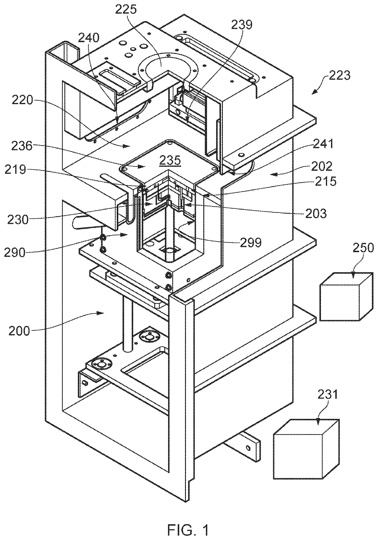
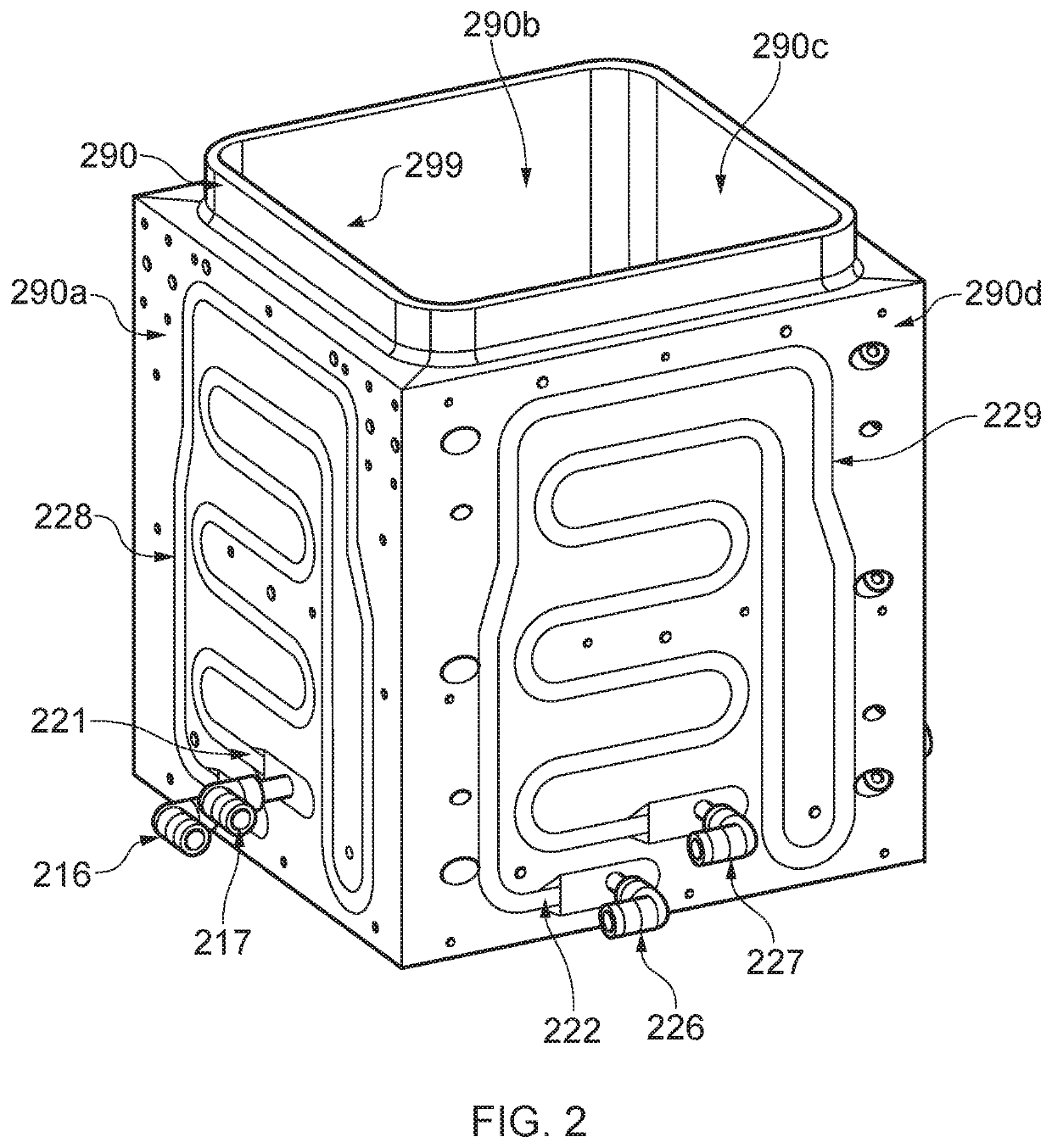
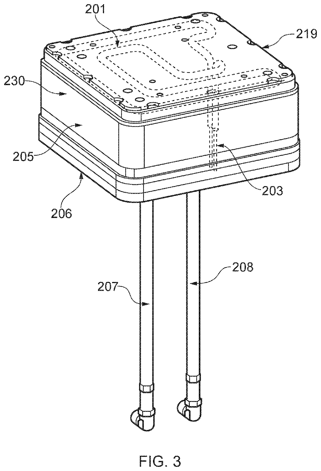
[0107]With reference to FIGS. 1 to 4, a powder bed fusion apparatus 223 according to an embodiment of the invention includes a build chamber 202 that can be sealed from the external environment. The build chamber 202 is divided into an upper processing chamber 220 and a lower chamber 200 by top plate 215 and a build platform 230 reciprocally movable within a bore 299 of a build sleeve 290. The build platform 230 is moved by an elevator mechanism (not shown) located in the lower chamber 200. The build platform 230 is sealably engaged with the bore 299 of the build sleeve 290 to prevent egress of powder into the lower chamber 200. This is achieved by seals 209, 210, 211 (see FIG. 4), associated with an edge of the build platform 230, which physically engage with the bore 299 of the build sleeve 290. The plate 215, build sleeve 290, build platform 230 and associated seals 209, 210, 211 function to form a barrier for the powder such that the powder remains in the processing chamber 220 ...


PUM

PropertyMeasurementUnit
Temperatureaaaaaaaaaa

Abstract

A powder bed fusion apparatus in which an object is built in a layer-by-layer manner. The apparatus includes a build sleeve, a build platform for supporting a powder bed and the build platform lowerable in the build sleeve. A heating element is integrated in or located on the build platform or the build sleeve. A seal is provided for sealing a gap between the build platform and the build sleeve to prevent powder from passing through the gap. A build chamber is provided for maintaining an inert atmosphere both above and below the build platform.

Description

[0001]This is a Continuation-in-Part of International Application No. PCT / GB2018 / 051109 filed Apr. 27, 2018, which claims the benefit of British Application No. 1706705.9 filed Apr. 27, 2017. The disclosure of the prior application is hereby incorporated by reference herein in its entirety.FIELD OF INVENTION[0002]This invention concerns powder bed fusion apparatus and methods in which selected areas of a powder bed are solidified in a layer-by-layer manner to form a workpiece. The invention has particular, but not exclusive application, to selective laser melting (SLM) and selective laser sintering (SLS) apparatus.BACKGROUND[0003]Powder bed fusion apparatus produce objects through layer-by-layer solidification of a material, such as a metal powder material, using a high-energy beam, such as a laser or electron beam. A powder layer is formed across a powder bed contained in a build sleeve by lowering a build platform to lower the powder bed, depositing a heap of powder adjacent to th...

Claims


Application Information

Patent Timeline
IPC IPC(8): B29C64/371B29C64/245B29C64/232B29C64/295
CPCB29C64/371B29C64/153B33Y40/00B29C64/232B33Y30/00B29C64/295B29C64/245B22F2999/00Y02P10/25B22F10/32B22F12/67B22F12/222B22F10/28B22F10/322B22F12/90B22F12/17B22F12/20B22F2203/11
Inventor MEINERS, WILHLEMEIBL, FLORIANKEMAKOLAM, NNEJISUTCLIFFE, CHRISTOPHER JOHNDERRER, JAN-PETERHUESKEN, CARLO
Owner RENISHAW PLC
Why Eureka
Try Eureka