
Optical fiber with modified distal end

a technology of optical fibers and distal ends, applied in the field of optical fibers, can solve the problems of inability to feed the fiber to the desired location, the inner surface of the endoscope/catheter may damage the distal end the difficulty of a practitioner to feed the optical fiber, etc., to achieve the effect of increasing the life span of the optical fiber, reducing the power energy source, and increasing the life of the optical fiber

Active Publication Date: 2020-03-12
LEONI KABEL GMBH
View PDF0 Cites 0 Cited by
  • Summary
  • Abstract
  • Description
  • Claims
  • Application Information

AI Technical Summary

Benefits of technology

The present disclosure relates to an improved optical fiber for use in medical procedures such as urology and nephrology. The patent describes a modified optical fiber that has a distal end with a specific shape that prevents contact between it and the inner lumen of a catheter or endoscope during placement within a patient. This prevents damage to the fiber and reduces the risk of needing to replace it, which would be costly and delay the procedure. Additionally, the modified fiber design allows for better breakage of stones using a lower power energy source. Overall, the patent provides an improved solution for using optical fibers in medical procedures.

Problems solved by technology

When feeding such an optical fiber through the endoscope / catheter the sharp edge may damage an inner surface of the endoscope / catheter, and complementarily, the inner surface of the endoscope / catheter may damage the distal end of the optical fiber.
Moreover, the sharp edge makes it more difficult for a practitioner to feed the optical fiber through the endoscope, especially if significant bending is necessary to place the endoscope / catheter, and thus the optical fiber, in proximity to a target site (e.g., the location of a kidney stone).
Such contact, consequently, leads to unwanted damage to the optical fiber (or catheter / endoscope) and may make it difficult feed the fiber to the desired location.
Additionally, such prior art devices are not of a unitary construction, and instead splice on the distal tip, which creates instabilities in the optical fiber and increases manufacturing costs.

Method used


Image

  • Optical fiber with modified distal end
  • Optical fiber with modified distal end

Examples


Embodiment Construction

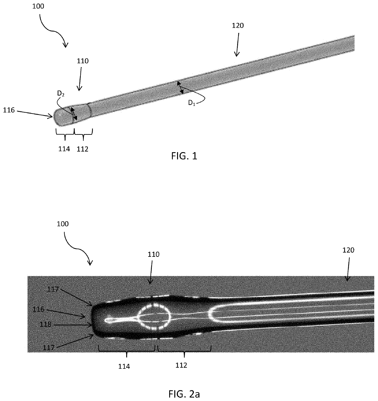
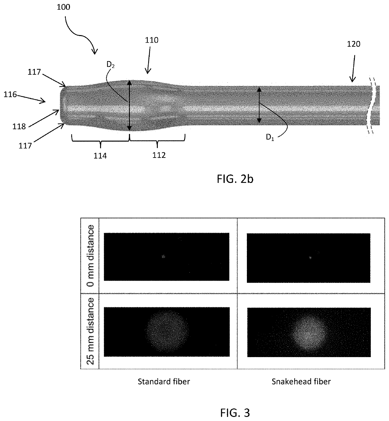
[0031]Detailed embodiments of the present optical fiber and methods are disclosed herein; however, it is to be understood that the disclosed embodiments are merely illustrative of an optical fiber, and methods that may be embodied in various forms. In addition, each of the examples given in connection with the various embodiments of the systems and methods are intended to be illustrative, and not restrictive. Further, the drawings and photographs are not necessarily to scale, and some features may be exaggerated to show details of particular components. In addition, any measurements, specifications and the like shown in the figures are intended to be illustrative, and not restrictive. Therefore, specific structural and functional details disclosed herein are not to be interpreted as limiting, but merely as a representative basis for teaching one skilled in the art to variously employ the present light emitting system, and methods.

[0032]With reference to FIGS. 1 and 2, an embodiment ...


PUM

PropertyMeasurementUnit
lengthaaaaaaaaaa
lengthaaaaaaaaaa
lengthaaaaaaaaaa

Abstract

An Optical fiber with modified distal end and related methods are provided. The optical fiber extends from a proximal end portion to a distal end portion and includes a core, a cladding, a coating, and an optional jacket. The distal end portion comprises a portion with an enlarged outer diameter.

Description

FIELD OF THE INVENTION[0001]This disclosure relates generally to optical fibers, methods of making optical fibers, and their methods of use. In particular, this disclosure relates to optical fibers with a modified distal end.BACKGROUND OF THE INVENTION[0002]Optical fibers have been implemented for a variety of light transmitting purposes. For example, optical fibers are well known for transmitting light from a light source to a delivery location. Such fibers may be implemented in a fiber-optic communication system to deliver light from a source (e.g., a cable provider) to a destination (e.g., a user's set-top box).[0003]Optical fibers as also well known for use in the medical field. For example, in order to ablate a kidney (or bladder) stone a doctor may insert an endoscope or catheter into a patient's urinary tract. An optical fiber may be fed through the endoscope / catheter to a location proximate to the stone. Radiation, typically from a holmium (Ho) laser, is directed through the...

Claims


Application Information

Patent Timeline
Patent Type & Authority Applications(United States)
IPC IPC(8): A61B18/22G02B6/02
CPCA61B2018/2244G02B6/02A61B2018/2288A61B18/22A61B2018/2205A61B2018/00511A61B2018/00517A61B2018/00577A61B2018/2266G02B6/0008G02B6/262
Inventor BOGATZKI, ANGELINASTOCK, PATRICK
Owner LEONI KABEL GMBH
Learn More