Check patentability & draft patents in minutes with Patsnap Eureka AI!

Oil scraper ring for a piston rod

a scraper ring and piston rod technology, applied in the direction of positive displacement liquid engine, pump components, engine seals, etc., can solve the problems of significant oil leakage and associated loss of oil, large design complexity, and high cost, so as to avoid the effect of superficial damage to the piston rod by the scraper ring and avoiding oil leakage into the cylinder

Pending Publication Date: 2020-03-26
HOERBIGER WIEN GMBH
View PDF2 Cites 0 Cited by
  • Summary
  • Abstract
  • Description
  • Claims
  • Application Information

AI Technical Summary

Benefits of technology

The invention is a new scraper ring design for an oil pump. The new scraper ring has several technical benefits. First, it eliminates the need for multiple separate scraper rings, which reduces the risk of oil leakage and damage to the piston rod. Second, a groove-shaped drainage opening is used to improve oil removal and simplify manufacture. Third, a recess is used to allow for easier mounting on the piston rod and improved compensation for wear. Overall, this new scraper ring design solves common issues and improves performance of the oil pump.

Problems solved by technology

In the process, the lubricating oil also passes to the piston rod and would be transported along the piston rod into the compression chamber in the cylinder, which is undesirable because on the one hand, this represents a significant oil leakage and an associated loss of oil.
On the other hand, the lubricating oil would be partially removed with the compression medium and contaminate the latter.
Such designs are relatively complex and therefore cost-intensive.
In addition, there is a limit in terms of size reduction due to the serial arrangement of multiple scraper rings with intermediate support rings, which is disadvantageous.
In some cases, when using two offset rings, only one scraping edge covers another, or if there are two scraping edges per ring, accordingly, only the two following scraping edges cover the gap of the first ring, which may lead to increased oil leakage.
The additional manufacturing and assembly costs in the execution as an assembly having multiple rings, which must be secured against rotation relative to each other, represents an additional source of error of classic scraping solutions.
These are often sized too small, however, which results in a damming or continuous wetting of the piston rod by the previously scraped lubricating oil, which reduces the scraping capacity of the next scraping edge.
Another problem with such metallic scraper rings is that the sharp scraping edge scratches against the piston rod and may damage it.
However, this increases the production costs of conventional scraper rings.
There are, however, also uncut scraper rings.
However, these rings always suffer the problems of not being able to adjust to wear, or only to a limited extent, and of being unable to sufficiently compensate for thermal expansions due to different thermal expansion coefficients of the material of the piston rod and of the scraper ring.

Method used


Image

  • Oil scraper ring for a piston rod
  • Oil scraper ring for a piston rod
  • Oil scraper ring for a piston rod

Examples


Embodiment Construction

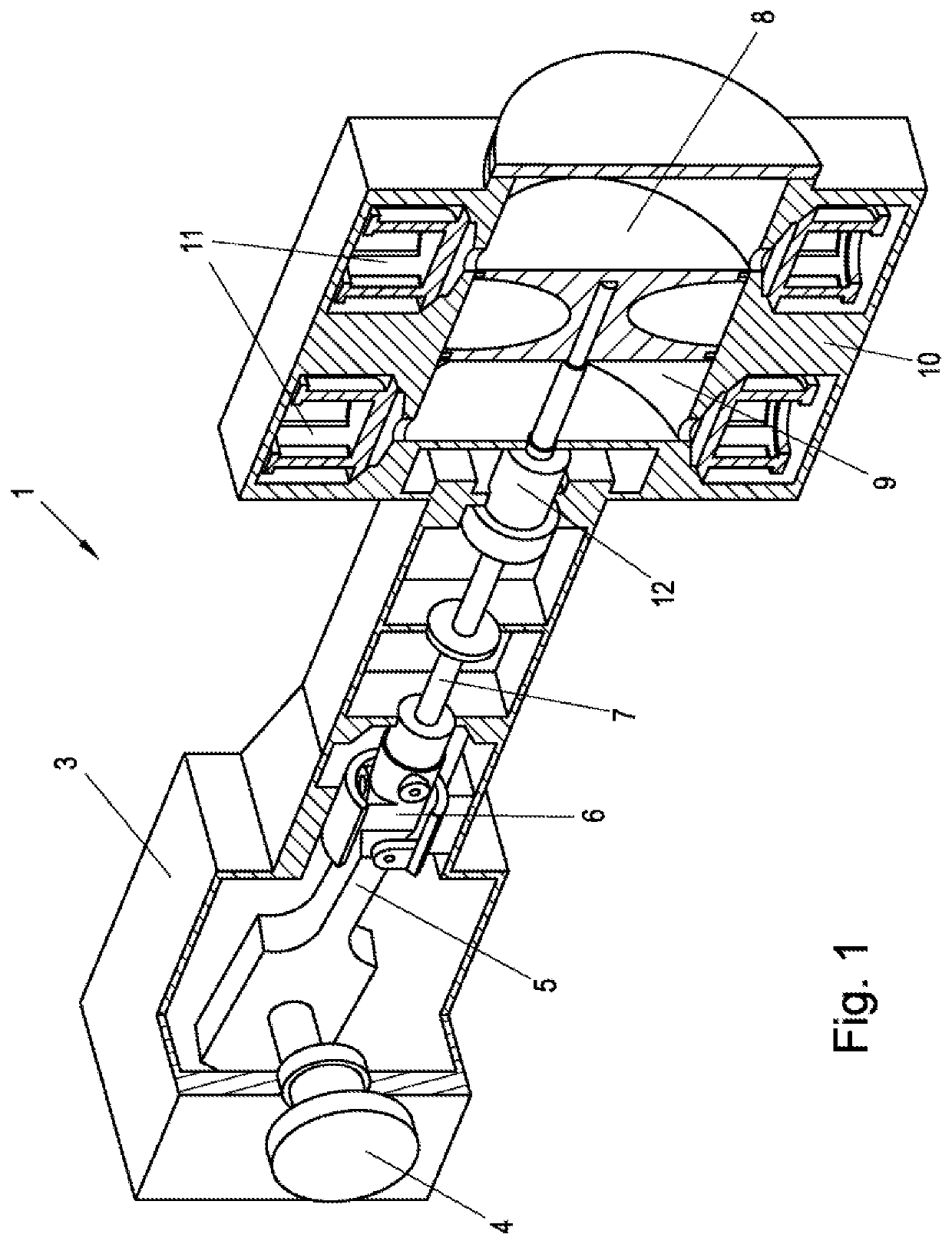
[0031]FIG. 1 shows by way of example a piston compressor 1, in which the scraper ring 2 according to the invention (see FIG. 2) may be used. The piston compressor 1 includes a compressor housing 3 (crankcase) in which a crankshaft 4 is rotatably mounted. A push rod 5 is rotatably mounted at one end on a so-called crank pin (not shown) of the crankshaft 4 and rotatably mounted with the other end on a crosshead 6. The crosshead is axially movably mounted in the compressor housing 3 and is provided to support the lateral forces acting on the crosshead 6 due to the rotational and translational oscillation of the push rod 5 radially on the compressor housing 3. One end of a piston rod 7 is arranged on the crosshead 6, the opposite end is connected to a piston 8, which is arranged in a cylinder liner 9 of a cylinder 10. From the crosshead 6, only a translational movement is transmitted via the piston rod 7 to the piston 8, as a result of which the piston 8 performs an essentially purely t...


PUM


Abstract

A scraper ring is provided with a plurality of sealing sections on the radially inner circumferential surface, each including a scraping edge, wherein the sealing sections are spaced axially apart from each other by inner circumferential grooves, with at least one recess provided on the circumference of the scraper ring which extends at least partially from a first axial ring end to a second axial ring end and extends at least partially in a direction different from the axial direction of the scraper ring. At least one drainage opening is provided on the outer circumferential surface of the scraper ring, which is connected to at least one inner circumferential groove for removing scraped oil from the inner circumferential grooves.

Description

CROSS-REFERENCE TO RELATED APPLICATIONS[0001]This application claims the benefit of priority to Austria application No. A 50808 / 2018, filed 20 Sep. 2018.BACKGROUND[0002]The invention relates to a scraper ring for scraping oil from a translationally oscillating piston rod, having at least one outer circumferential groove provided on the radially outer circumferential surface for receiving an annular spring for radially pretensioning the scraper ring, wherein a plurality of sealing sections, each having a scraping edge, is provided on the radially inner circumferential surface of the scraper ring, wherein adjacent sealing sections are spaced axially apart from each other by an inner circumferential groove, wherein at least one recess radially penetrating the scraper ring is provided on the circumference of the scraper ring, which extends at least partially from a first axial ring end of the scraper ring to a second axial ring end of the scraper ring, in order to produce an adjustabili...

Claims


Application Information

Patent Timeline
IPC IPC(8): F16J9/20F02B75/40
CPCF02B75/40F16J9/203F04B39/041F16J15/26F16J15/3232F16J15/3272F16J15/56F16J9/20
Inventor JANKO-GRASSLOBER, MARIANLAGLER, MARTINKAUFMANN, ANDREAS
Owner HOERBIGER WIEN GMBH
Features
  • R&D
  • Intellectual Property
  • Life Sciences
  • Materials
  • Tech Scout
  • Unparalleled Data Quality
  • Higher Quality Content
  • 60% Fewer Hallucinations
Learn More