Check patentability & draft patents in minutes with Patsnap Eureka AI!

Magnetic resonance receive coil with detune circuit and energy harvesting circuit

a magnetic resonance and receive coil technology, applied in the field of magnetic resonance devices with a detune circuit and an energy harvesting circuit, can solve the problems of b1-field inhomogeneity, image quality degradation, and loss in the structure, and achieve low losses in the operating (receiving) state, without significant loss of detune performance

Active Publication Date: 2020-03-26
KONINKLJIJKE PHILIPS NV
View PDF0 Cites 1 Cited by
  • Summary
  • Abstract
  • Description
  • Claims
  • Application Information

AI Technical Summary

Benefits of technology

The invention is a magnetic resonance receive coil with a detune circuit and an energy harvesting circuit. This results in efficient energy harvesting without significant loss of detuning performance. The detuning and energy harvesting arrangement is simple and easy to manufacture without demanding additional space. The invention also utilizes the coil loop for detuning and matching, which further reduces space requirements. The resonator is a transmission cable, such as a coaxial cable, which provides flexibility and allows for a high degree of mechanical flexibility with the magnetic resonance receive coil. The invention improves the performance of the magnetic resonance system as a whole.

Problems solved by technology

Such wireless power scheme will result in B1-field inhomogeneity due to pick-up coil interference.
As a consequence of B1-field inhomogeneity, the image quality will degrade.
These inductive elements typically dominate the losses in the structure.
Furthermore, a low loss inductor for very efficient detuning or matching needs much space.

Method used


Image

  • Magnetic resonance receive coil with detune circuit and energy harvesting circuit
  • Magnetic resonance receive coil with detune circuit and energy harvesting circuit

Examples


Embodiment Construction

[0024]Detailed description of the present invention is given below in connection with the accompanying drawings.

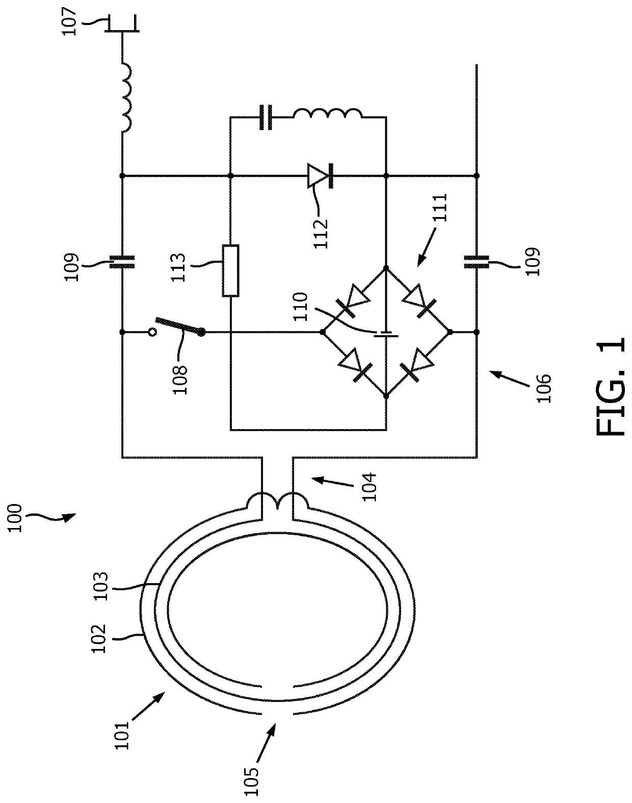
[0025]FIG. 1 illustrates one possible embodiment of a radio frequency receive coil 100 including a resonator 101 with an energy harvesting circuit 106 for use in a magnetic resonance imaging system.

[0026]The radio frequency receive coil 100 comprises a resonator 101 for receiving radio frequency signals emitted by nuclei in a magnetic resonance examination by a subject under examination. The resonator 101 comprises two conducting elements 102, 103 that are insulated from each other. The first conducting element 102 of the resonator 101 has a conductive loop and forms part of an radio frequency receiver coil 100 that is tuned to at least one first resonance frequency. The resonator 101 can be made resonant by choosing the correct length of the first conducting element 102 and the second conducting element 103. The resonator 101 is further tuned by adjusting the relative per...


PUM


Abstract

The invention relates to a magnetic resonance receive coil including a resonator for use in a magnetic resonance imaging system. The radio frequency receive coil according to the invention comprises a first conducting element of the resonator having a conductive loop wherein the received signal is induced in that loop, configured to form a primary resonant circuit tunable to at least one first resonance frequency and a second conducting element of the resonator configured to form an electric circuit electrically insulated from and reactively coupled to the primary resonant circuit, the electric circuit being adapted to detune the primary resonant circuit to at least one second resonance frequency. The second conducting element of the resonator has a conductive loop with a pair of ends connected to a preamplifier. The radio frequency receive coil further comprises an energy harvesting circuit electrically coupled in parallel over the pair of ends of the second conducting element, wherein the energy harvesting circuit is adapted for being connected to the second conducting element during transmission by a switch. A rechargeable power source is coupled to the energy harvesting circuit, wherein the rechargeable power source is adapted for being charged by the energy harvesting circuit. A switching component is circuited in parallel to the energy harvesting circuit, wherein is adapted to redirect a current as soon as the rechargeable power source is charged to a sufficient voltage. In this way, a magnetic resonance receive coil with a detune circuit and an energy harvesting circuit for energy harvesting is provided without a significant loss of detuning performance.

Description

FIELD OF THE INVENTION[0001]The invention relates to the field of magnetic resonance devices, and in particular to magnetic resonance devices with a magnetic resonance receive coil with a detune circuit and an energy harvesting circuit.BACKGROUND OF THE INVENTION[0002]Magnetic resonance methods, which utilize interaction between magnetic field and nuclear spins in order to form two-dimensional or three-dimensional images, are widely used nowadays, notably in the field of medical diagnostics.[0003]Usually, magnetic resonance imaging (MRI) systems comprise a superconducting main magnet for the generation of static B0-field in an examination zone, gradient coils for the generation of switched magnetic field gradients during the imaging sequence, and a radio frequency coil assembly. The radio frequency coil assembly of known MRI systems includes a transmit coil to generate B1-field for excitation of nuclear spins, and one or more receiving antennas used in conjunction with the transmit ...

Claims


Application Information

Patent Timeline
IPC IPC(8): G01R33/36H02J50/12H02J7/02
CPCH02J7/025H02J50/12G01R33/3607G01R33/3621G01R33/3628G01R33/36A61B5/055G01R33/34007G01R33/341G01R33/3657G01R33/3692H02J50/005H02J7/0068H02J2310/23
Inventor FINDEKLEE, CHRISTIANLIPS, OLIVER
Owner KONINKLJIJKE PHILIPS NV
Features
  • R&D
  • Intellectual Property
  • Life Sciences
  • Materials
  • Tech Scout
  • Unparalleled Data Quality
  • Higher Quality Content
  • 60% Fewer Hallucinations
Learn More